Table of Contents
Advertisement
Advertisement
Table of Contents

Related Manuals for Lorenzoni LOR-THERM 355

Summary of Contents for Lorenzoni LOR-THERM 355
- Page 1 INSTRUCTION MANUAL LOR-THERM 355 Cod. 523.0000.100...
- Page 2 For the guarantee to be valid, the product must be installed and handled as indicated in this manual. This means it is extremely important that you read the manual. This applies both to the person installing The thermostat and the person who will use it. You will also find technical specifications and information on troubleshooting.
-
Page 3: Table Of Contents
This is your thermostat ......32 In the box ..........33 Installing the thermostat ...... 34 Getting started .......... 37 How the thermostat works ....38 Symbols on the display ......45 How to set the thermostat ....46 Energy saving programs ...... -
Page 4: This Is Your Thermostat
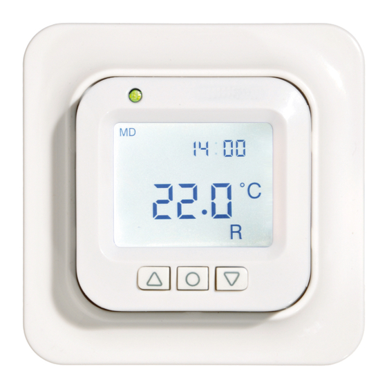
This is your thermostat This is a microprocessor-controlled thermostat with LCD display. The dis- play is backlit and stays lit for 30 sec- onds after the last push of a button. The front is fitted with an LED and three control buttons. -
Page 5: In The Box
In the box 1. Front for Elko and Gira 2. Adapter for Strömfors frame system 3. Front for Eljo Trend, Merten 4. Frame 5. Thermostat 6. Floor sensor 7. Connection clip Manual Quick guide... -
Page 6: Installing The Thermostat
Installing the thermostat The thermostat must not be Important located somewhere it is exposed to the following: • direct sunlight and draughts. • extreme fluctuations in temperature or high air humidity. The floor sensor should be mounted in a spiral hose laid in the floor. The hose end- ings should be sealed so that the floor sensor can easily be replaced. - Page 7 is connected with a connection clip in the box. See wiring diagram below. 4. Insert the thermostat into the ap- pliance box and screw tight with the existing screws. 5. Fit the frame and front. 6. If the thermostat is mounted in a multi-compartment frame, the internal corners of this frame must be removed.
-
Page 8: Getting Started
Getting started After installation, wait 2-4 weeks before starting the underfloor heating. Exactly how long you wait depends on the type of floor you have and the instructions for the floor putty. Then increase the heat gradually. There is a quick guide so that you can easily get started with the thermostat. -
Page 9: How The Thermostat Works
How the thermostat works This section describes all you need to know about how the thermostat works. To learn how to enter settings to suit your own requirements, read the sec- tion How to set the thermostat. Time Temp Selected control Select button [ Display Turn on the LCD display’s backlight by... - Page 10 enter personal settings is described in the section How to set the thermostat. There is an explanation of the symbols on the display in the section Symbols. Using the buttons The buttons are used to raise and lower the temperature as well as navigating the menus.
- Page 11 The heating is not controlled in stand- by mode. The clock runs as normal and programmed times and temperatures remain in the memory. Locking the keypad The keypad can be deactivated to prevent anyone touching the buttons by mistake. This is shown with the lock symbol in the display.
- Page 12 Time and date Time can be shown in 12- or 24-hour format. The correct day of the week is worked out automatically. The calendar resets itself in leap years and adapts to DST. Read how to set the correct time and date in the section How to set the thermostat/Time and date.
- Page 13 Delay between turning off and on There is a built-in delay in order to avoid unnecessary wear and tear on internal components and to extend the life of the thermostat. If you raise the desired temperature so that the thermostat comes on, and then lower it shortly afterwards, it takes 30 sec before it goes off again.
- Page 14 Flashing green and red light – error indication. The underfloor heating is turned off. The thermostat shows error messages until it is switched off. Find out more under Error codes. No light – the thermostat is switched off or is not getting any power. Control functions The thermostat can regulate the tem- perature in three different ways.
- Page 15 Room and floor thermostat – The built-in sensors regulate the room temperature and the sensor in the floor functions as a floor temperature limiter. The limitation can be set to between 5°C and 45°C. The factory setting of 35°C gives a surface temperature of approx.
-
Page 16: Symbols On The Display
Symbols on the display 1. Day of the week 2. Time and date 3. Selected menu/Current temp (actual value) °C 4. Set temp (set point) °C 5. Selected control 6. Shows that a program is running 7. Lock symbol 8. Program 9. -
Page 17: How To Set The Thermostat
How to set the thermostat This section describes how to set your thermostat to suit your require- ments. By entering these settings you can adapt the underfloor heating sys- tem to your own heating requirements as much as possible. If you want to find out more on how to navigate the menus or use the keypad, read the section How the thermostat works. - Page 18 Light and contrast Set the light intensity of the LED Press and navigate to SET. Select with . Navigate to LED and select with . Navigate between LED L (weak light) and LED H (strong light). Confirm with Set display contrast Press and navigate to CONT.
- Page 19 Set time format Press and navigate to SET. Select with . Navigate to DISP and select with . Navigate between 12- and 24-hour format. Confirm with . Turn off DST The calendar switches to DST automat- ically. This function can be turned off. Press and navigate to SET.
- Page 20 Control functions These are described in more detail in the section How your thermostat works/ Control functions. Select control function Press and navigate to SET. Select with . Navigate to RNF and select with . The icon for the current function (R, F or R&F) flashes.
-
Page 21: Energy Saving Programs
Energy saving programs A smart way to save energy is to adapt the heating to your actual daily requirements and, for example, lower the temperature when the house is empty. There are four program options for temperature reduction in your thermostat: two preset programs for home and office environments, one program which is based entirely on... - Page 22 Select with and the program starts. When a program is running the icon is displayed together with . Stop a program Press and navigate to PROG. Select with . The current program icon flashes. Navigate until none of the icons are flashing and confirm with .
- Page 23 You can set four events for every day: wakeup home and night . When programming you specify the desired time and temperature for every event. Preset means that the program runs every day, but you can also programme each day individually. Press and navigate to SET.
- Page 24 Night is shown. Repeat the steps above to set time and temperature. If one of the days of the week requires different settings, do as follows: Press and navigate to SET. Select with . Navigate to 4E, select with . Now you will see .
- Page 25 regulates the temperature in line with this. The normal settings remain in the memory and the thermostat reverts to them when the frost protection program is deactivated. Temperature can be set to a level be- tween 5°C and 15°C, the factory setting is 10°C.
-
Page 26: Troubleshooting
Troubleshooting The underfloor heating Important system is an electrical power installa- tion and any faults must therefore be remedied by a qualified electrician. Error codes When an error occurs, the thermostat will turn off the heating. The LED flashes alternately in red and green. The LCD display shows a flashing error code, while the display shows the following texts: Error 1: Short circuit room sensor. -
Page 27: Technical Specifications
Technical specifications Voltage 230 VAC-50 Hz Air temp. range 5-37°C Floor temp. range 5-37°C Temp. limiter 5-45°C Breaking capacity 3600 W/16 A/230 VAC Main switch single-pole Connection cable max 2.5 mm Load cosφ= 1 Hysteresis +- 0.3°C Protection class IP21 Back up time 36 h Max. - Page 28 Accessories Dimensions Article (mm) Extension frame 81x81x29 Sensor cable 3 m (included) Back plate, 86x86x6 polar white...