Table of Contents
Advertisement
Quick Links
Advertisement
Table of Contents

Related Manuals for MyFlyDream MFD AAT


Summary of Contents for MyFlyDream MFD AAT
- Page 1 MyFlyDream Automatic Antenna Tracker Manual V 3.0 www.MyFlyDream.com...
-
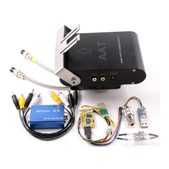
Page 2: System Components
Notes Thank you for purchasing the MyFlyDream Automatic Antenna Tracker (hereinafter referred to as MFD AAT). Please follow this manual to get familiar with the tracker and to operate it correctly. The tracker is a precision mechanical and electronic device. Please read this manual carefully to avoid damaging the device or hurting yourself and others. -
Page 3: Working Principle
But any high-gain antenna is accompanied by a narrow effective angle. MFD AAT is designed to solve the difficulty to keep the directional antenna pointed at the target to ensure the best possible reception and transmission during FPV flight. -
Page 4: Connection And Setup
TeleFlyOSD: Weight (Not including the harness) Size 45 * 25 mm Input voltage 7~20V (7~13V if connected with an ExtensionBoard) Current consume 100mA AATDriver: Weight Size 78*44*23mm (Length*Wide*Height) Input voltage Current consume 100mA Virtual GPS 1200bps Communication *Virtual GPS: AATDriver can virtualize itself as a bluetooth baud rate GPS module. - Page 5 Part # Name Extension board port OSD video signal port UP button SET button DOWN button Connecting pins Firmware upgrade socket Wires color and function Colour Name Remard Power Power input Black(3 wires) Ground Blue SetHome Set the tracker position Green GPS Data GPS Data...
- Page 6 configuration, the TeleFlyOSD powers the GPS. In the diagram, the operating voltage of GPS is assumed to be 3.3V. If your GPS needs an operating voltage of 5V, refer to Appendix A. Please refer to Connection Diagram B if a GPS is shared with another component (OSD, Autopilot).
- Page 7 Connection Diagram A (power the GPS by TeleFlyOSD)
- Page 8 Connection Diagram B (share GPS with other OSD)
- Page 9 Selecting appropriate baudrate for TeleFlyOSD Since the output data rate of different GPS may be different, it is necessary to set the baudrate of the TeleFlyOSD communication port to match the GPS used. There is a two-way DIP switch on the backside of the TeleFlyOSD module which is used to select baudrates: The arrow-indicated DIP switch in the figure has an ON mark above.
- Page 10 2). Mounting tracker and AATDriver Please mount the antenna on the antenna handler of the tracker firmly. The image transmission receiver is suggested to be mounted on the antenna handler to avoid interference. Antenna cables tend to be stiff, continual bending due to the electronmagnetic movement of the tracker might damage it.
- Page 11 3).Preliminary system test Power on the AATDriver with 12V DC. The red LED and yellow LED on the AATDriver will flash for several times and then go out. Flashing 5 times means the data output of the AATDriver is currently in MFD mode and flashing 2 times means it is in VGPS mode.
- Page 12 5. How to use the AAT Power on all equipments and use the test button on the AAT Driver to check the tracker. Check to ensure the four pointing directions are basically correct and the red RX LED on the AATDriver flashes continually. It takes time for the GPS to search satellites.
-
Page 13: Advanced Usage
6. Advanced Usage Setup and operation of the tracker There are 3 LED indicators and buttons on the right side of the tracker. From left to right, the buttons (LEDs) are: Off-Line (Red) North (Yellow) Cal. (Green) Common functions and operations of the tracker: Function How to operate Remark... - Page 14 Description of the tracker LED indicators: Indicator Status Meaning The tracker is tracking. The tracker is in off-line mode. Off-Line The tracker stands by. If you have set home (Red Light) Flashing position, the tracker will start to track once the target moves 10 meters away.
- Page 15 After removing the left panel you will see there are 7 soldering pad on the PCB. They are numbered from 1 to 7. A 6 channels tracker has only a 6 pin plug. The Aux Channel 1 maps to PIN#3 of the plug.
- Page 16 the HOME button, the yellow and the red lights of AATDriver will blink several times. 2 times means the tracker is currently in VGPS mode, 5 times in MFD mode. Set the origin The current location of the aircraft will be Press Home coordinate for...
- Page 17 MFD protocol contains more information about the plane than VGPS mode. 1200bps You can use the ground station software provided by MyFlyDream to check the data. Currently it runs on the J2ME platform (need JSR82 support). The android version is also coming soon.
- Page 18 MIDP 2.0, and also support the Bluetooth API (JSR 82) to run it. The FDStation software can be downloaded from: http://www.myflydream.com/Help1.aspx After installing and running the software, search for the AATDriver and use 1234 as password to establish a connection.
- Page 19 DataView :...
-
Page 20: Osd Functions
PathView: Keys definition of the FDStation software: Left: Toggle between DataView and PathView Right: Rotate the screen 90 degrees in DataView Up/Down: Scroll the screen in DataView mode Zoom in/Zoom out in PathView mode 7. OSD Functions The TeleFlyOSD provides OSD functions that can overlay the flight information on the video picture. - Page 21 There are invalid Vid-in and Vid-out marks on the TeleFlyOSD PCB of some batches. Please use the above description. Purpose of the three buttons numbered 3, 4 and 5 in the picture: Part # Name Remark UP Button Select the previous item SET Button Enter a menu list,Or change the current item DOWN Button...
- Page 22 By pressing the “SET” switch, you can enter the following interface of system options: To change options, use the “UP” and “DOWN” buttons to move the marker to the appropriate option and press the “SET” button. This is a screenshot of a real flight:...
- Page 23 Options menu: Item Remark Press the SET button repeatedly, and VER OFFSE value will vary VER OFFSET between -16 to 15, the whole OSD screen picture moves the corresponding pixels in the vertical direction. Press the SET button repeatedly, and HOR OFFSE value will vary HOR OFFSET between -16 to 15, the whole OSD screen picture moves the corresponding pixels in the horizontal direction.
- Page 24 2). Q: How to make the data downlink more reliable? MFD AAT uses the audio channels to transmit data. A clean noise-free audio channel with appropriate level can make the data transmission more reliable. It is suggested the peak-to-peak value of audio output level of the video transmission receiver should be preferably within 0.8~2V.
- Page 25 Especially the lawmate 1.2G 100mw VTX has audio problem. It is not able to transmit the audio signal clearly. User need to solder 22~45pf capacitor to fix this issue. the added capacitor should be connected in parallel with the green component beside the red arrow, as the below picture shown.
-
Page 26: Related Resources
8. Related Resources MyFlyDream website: www.MyFlyDream.com The Post discussing the tracker on RCGroups.com: http://www.rcgroups.com/forums/showthread.php?t=1159128 Tracking demo video of the tracker: http://vimeo.com/36695133 http://www.youtube.com/watch?v=HKCc3vOvqzg... -
Page 27: Appendix A: Pins And Functions Of
Appendix A: Pins and Functions of TeleFlyOSD There are two rows of pins spacing 2.54mm (0.1inch) at one end of the TeleFlyOSD. The pins are numbered as follows: Color of PIN # Name Remark the Wire Connect to the audio input of the AV White Audio output transmitter... - Page 28 Orange 3.3V output Used to supply power to a 5V GPS. Green Data Input Connect to the GPS data output...
-
Page 29: Appendix B: Connection Diagram Of Some
Appendix B: Connection Diagram of Some Common GPS Modules LS20033 Description PIN# Name 3.3V Power input Ground Data output (TTL level) VBackup Backup battery supply voltage Connection Diagram CAUTION: GPS PIN#1 and PIN#6 MUST be connected to +3.3V. This GPS doesn’t work without PIN#6 connecting to VCC. -
Page 30: Appendix C: Teleflyosd Firmware Update
Appendix C: TeleFlyOSD Firmware Update Steps Download programs and firmware packages required for update from http://myflydream.com/Help1.aspx Connect the USB programmer to the update socket of the TeleFlyOSD: Run this file: (Do not try to rename the file, it won´ t work ... - Page 31 Click the LoadProject button to open the firmware to be updated, e.g., TeleFlyOSD_v1_1.xwpprj.
- Page 32 Click the “AUTO” button and wait for about 20 seconds until the update is done. ...
Need help?
Do you have a question about the MFD AAT and is the answer not in the manual?
Questions and answers