Table of Contents
Advertisement
Quick Links
Advertisement
Table of Contents

Related Manuals for Eltek Flatpack MCU


Summary of Contents for Eltek Flatpack MCU
- Page 1 User’s Guide Monitoring and Control Unit Flatpack DC Power Supply Systems...
- Page 2 Information in this document is subject to change without notice and does not represent a commitment on the part of Eltek Energy. No part of this document may be reproduced or transmitted in any form or by any means —...
-
Page 3: Table Of Contents
9 and 25-pin D-sub plugs........................21 4.2.3 Remote Installation ........................... 22 4.2.4 RS-232 Cable pinouts – Remote Connection .................... 23 4.2.4.1 Cable from Flatpack MCU to Modem ....................23 4.2.4.2 Cable from modem to PC ........................23 4.2.5 Modem Configuration..........................24 4.2.5.1 Setting up the PRS (remote) modem..................... - Page 4 4.12 ............................... 66 ASSWORDS 4.13 ..............................66 LARM 4.14 ............................67 ATTERY 4.14.1 Battery Test Log............................68 4.15 ............................69 LEAR VENT 4.16 ............................. 69 ESYNCH YSTEM RANGE OF SETTINGS AND DEFAULT VALUES..................69 Operation Guide Flatpack MCU, 351300.013, v8-2006-07...
- Page 5 Contents Operation Guide Flatpack MCU, 351300.013, v8-2006-07...
-
Page 6: Introduction
1 Introduction 1 Introduction Eltek Energy is a world leader in the development of new power supply systems, designed to meet the rapid growth within the field of telecommunication, as well as the increasingly stringent reliability requirements. With the introduction of microelectronics in electronic equipment, energy distribution and telecommunication and data... -
Page 7: Equipment Features
The Flatpack MCU alarm module may be connected to rectifier systems where Flatpack rectifiers are installed. With Flatpack MCU installed in the rectifier system, the MCU`s front keypads and display can be used to monitor, interrogate and operate the system. Flatpack MCU provide connectivity for remote monitoring and control, either via WinPower Silver communication software, WebPower web browser interface, or via an SNMP-agent to an NMS. -
Page 8: Communication Protocols
• pComm binary master-slave communication protocol TE241241.000-B4 • COMLI - a serial master-slave protocol used to interface the Flatpack MCU with a modem or PLC. For details of the protocol, see TE36862-B4 "COMLI communication protocol implemented in PRS systems". 2.1.3 WinPower Silver communication software WinPower Silver is the main user interface for the Flatpack MCU, when communicating from a PC. -
Page 9: Firmware Upgrade Of The Mcu Controller
“UPGRADING FW, PLEASE WAIT…” When the firmware is completely loaded, the MCU controller will automatically restarts. Only version 3.10 or above. You can get a copy of the FWLoader progam by contacting Eltek’s Service Dep. Operation Guide Flatpack MCU,... -
Page 10: Local Operation Of The Flatpack Mcu
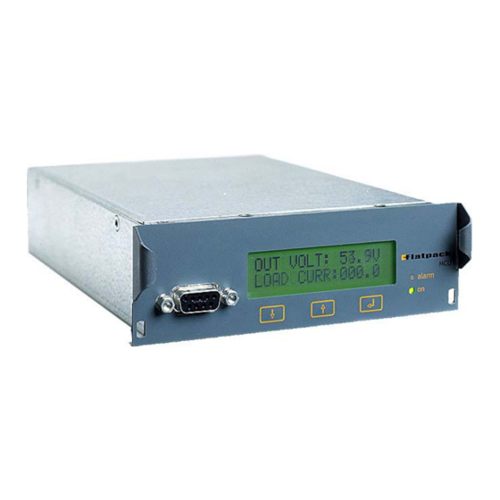
The Flatpack MCU control panel consists of a three-button keypad, a graphic display, a 9-pin D-Sub female plug, a green LED (indicating that the system is ON) and a red LED (indicating that the system is in the alarm mode). -
Page 11: The Front Display
3 Local Operation of the Flatpack MCU 3.1.1 The front Display The Flatpack MCU Alarm Module incorporates a dot matrix display (16x2) with background illumination. The lower line shows Outp.Voltage : 52.8V The upper line shows information about currents, Mains Alarm... -
Page 12: Hierarchy Of Menus
Test End Volt Batt Test Setup Max Test Duration Test Interval Test Delay Period Most menus in Flatpack MCU can be accessed when the Start/Stop Test Start Test/Stop Test Rectifier system is operated from the keypad of Flatpack Charge Curr Lim Enable/Disable MCU. -
Page 13: Menu Options
All alarms in the system are — as default— automatically reset, when the cause of the alarm is removed. Nevertheless, Flatpack MCU enables you to reset all active alarms that are configured as manually resettable alarms. Alarms still active after resetting will be reported again; refer to chapter 4.9.2 Alarm Setup/Display. -
Page 14: Display Important System Voltages (Voltage Info)
Display Alarm Messages (Display messages) The Flatpack MCU stores all system events chronologically in a message buffer. This menu option is used to browse through the buffer’s alarm messages. The messages are presented on the lower line of the display, one message at a time. The last message will be displayed first. -
Page 15: Adjustment Of Important System Voltages (Voltadsjustment)
3 Local Operation of the Flatpack MCU 3.3.8 Adjustment of Important System Voltages (VoltAdsjustment) The menu option VoltAdjustment, in Service Options, enables adjustment of the following system voltages: HighBatt 2 NomVolt Voltage limit for High Battery Alarm 2 Nominal output voltage... -
Page 16: Auto Boost Configuration (Auto Boost Cfg)
3Local Operation of the Flatpack MCU Check that boost time and voltage are configured with the correct values. For Hierarchy of Menus, see page 12 3.3.13 Auto boost configuration (Auto Boost Cfg) From auto boost configuration menu the operator can set the following auto boost parameters... -
Page 17: Battery Setup (Battery Setup)
This menu option, in the Service Options menus, enables selection of the type of control on the output voltage. The output voltage can be controlled in three different ways: Preset Rect.Volt The output voltage is not controlled by the Flatpack MCU, but by the rectifier module — factory preset (refer to the rectifier manual). Temp.Comp. -
Page 18: Change Date And Time (Change Date/Time)
3.3.20 Change date and time (Change Date/Time) This menu option, in the Service Options menus, allows the date and time in Flatpack MCU to be changed. The Date and time are used for different purposes: Alarm /Message Log Indicates when an alarm or event occurred in the system. -
Page 19: Baud Rate Adjustment (Set Baud)
To be able to use a modem with the Flatpack MCU the modem sense must be ON In order to use certain other devices with the Flatpack MCU, modem sense must be OFF (example, Eltek’s WebPower adapter). If not using a modem with Flatpack MCU, it is recommended that modem sense be set to OFF. -
Page 20: Operating From A Personal Computer
4 Operating From a Personal Computer 4 Operating From a Personal Computer The rectifier system can either be operated from the Flatpack MCU— by means of the keypad on its front panel— or from a standard personal computer. Operation from the front keypads enables control of important system functions and parameters; the use of a... -
Page 21: Rs232C Cable Pin-Outs - Local Connection
The serial cable in this figure can be used on PC's with 9-pin D-sub male plugs. The serial cable is connected to the 9-pin D–sub female plug on the Flatpack MCU and to one of the PC's serial ports (COMx). -
Page 22: Remote Installation
NOTE: When using a modem: Access to an AC mains wall outlet supply may be necessary to connect the modem to the PC. The modem connected to the Flatpack MCU is normally fed from the DC-bus. Only true analog modems are supported (switchboard and other digital/PBX... -
Page 23: Rs-232 Cable Pinouts - Remote Connection
The serial cable connecting the MCU to the modem may be either a 9 pin connection or 25 pin connection at the modem depending on the modem type. The serial cable in the drawing below is connected to the 9-pin D-sub male plug on Flatpack MCU and to the 25-pin D-sub male plug on the modem’s port. -
Page 24: Modem Configuration
Setting up the PRS (remote) modem In order to configure the remote modem— to be connected to the Flatpack MCU Monitoring & Control Unit— connect the modem to a PC, with the appropriate terminal emulation program, and use the keyboard... -
Page 25: Login To Winpower Silver
4 Operating From a Personal Computer Login to Winpower Silver To login, first establish the communication link between your PC and the Flatpack MCU alarm module. Start WinPower Silver and click on the “lightning bolt” connection icon to open the Site Manager. -
Page 26: Using Site Manager
Ethernet Network adapter is a separate solution than WebPower). Modem refers to a connection to a Flatpack MCU, at a given remote site, to the PC. Reference Section 4.2.3. Site entries under this category will connect using a modem connected to and installed on the PC, to the remote sites equipped with a modem connected to the Flatpack MCU. -
Page 27: Description Of The Screen Interface
Description of the Screen Interface After establishing the communication link between your PC and the rectifier system, the Flatpack MCU microprocessor will take control of the PC screen. Operation of the rectifier system from a PC is based on pre-programmed menus accessed from the main menu. -
Page 28: Main Menu
• Select "Password" • Enter your password (factory-programmed to «service») • Press Enter ↵ or Login For security reasons, we strongly advise you to change factory-programmed passwords as soon as the system is installed Operation Guide Flatpack MCU, 351300.013, v8-2006-07... - Page 29 • Clear Event Log Clears the log of events on the screen interface • Resynch system Updates specific data from MCU to Winpower Silver • About Shows information about Winpower Silver Operation Guide Flatpack MCU, 351300.013, v8-2006-07...
-
Page 30: Other Main Menu Options
To update the values again, the user has to press Update. Reset Pressing the reset button can reset the logging values. The following dialog will appear: Operation Guide Flatpack MCU, 351300.013, v8-2006-07... -
Page 31: Symmetry Monitor
To open the Symmetry Monitor, select Symmetry Monitor on the View menu. The Symmetry Monitor is an auto-updating window that shows you the current symmetry voltages, Type, Status, Mode and Remaining delay time. (Symmetry is disabled in the picture above) Operation Guide Flatpack MCU, 351300.013, v8-2006-07... -
Page 32: Alarm Status Screen
Note that all alarm events, whether automatically or manually reset, are reported to the Flatpack MCU alarm history log. •... -
Page 33: General Configuration
4 Operating From a Personal Computer General Configuration 4.9.1 Set Levels - Setting alarm limits This menu option is used to set alarm limits and other system parameters. Operation Guide Flatpack MCU, 351300.013, v8-2006-07... - Page 34 NOTE: Hysteresis on High Temperature 1 and Low Temperature alarms is 1°C; hysteresis on High Temperature 2 is 2°C. NOTE: The temperature alarm-functions are available, and the set points are changeable, only when temperature-compensated charging is activated. Operation Guide Flatpack MCU, 351300.013, v8-2006-07...
-
Page 35: Alarm Setup/Display
NOTE: In the above screen capture, Configurable Input 1 has been renamed “HVAC Fault” and is assigned to a modem. Also, High Temperature 2 is mapped to LVD1 and will disconnect this LVD contactor when the temperature limit is reached. Operation Guide Flatpack MCU, 351300.013, v8-2006-07... - Page 36 This alarm is reported if one or more alarms are active and is indicated by the Alarm LED Automatic reset when no active on the front panel of Flatpack MCU and by Alarm ON (OFF) on the status lines (except alarms remain...
-
Page 37: Configurable Inputs
4.9.3 Configurable Inputs The Flatpack MCU incorporates 5 digital inputs, providing a means to monitor other on site equipment through the Flatpack MCU and WinPower Silver interface. In the above setup, two alarm inputs are configured for monitoring a generator set, and a burglar alarm. The texts are freely chosen and must be within 13 characters. - Page 38 Input configured as DISABLED: disables the configurable input. Input is configured as ALARM: The Flatpack MCU will enter alarm condition on either an open or short circuit condition, depending on the state of the “failsafe” checkbox. When the checkbox is selected (“ticked”), an open circuit on a particular input (to AGND) will cause an alarm condition, and a shorted input (closed contacts) clears the alarm.
-
Page 39: Set Time
The parameters are entered in the correct format, date: «YYYY-MM-DD», and time: «HH:MM». Note that the Flatpack MCU prior to Version 10 does not incorporate a real time clock with battery backup – if a pre- version 10 MCU is powered down, the correct date and time must be re-entered after restoration of power. The date and time must be set in order for a valid timestamp to appear in the Event and Alarm logs. -
Page 40: Site Info
4.9.5 Site Info This menu option enables you to adapt the Flatpack MCU to a site specific installation, by registering site-related information such as the name of the customer/owner, location, serial numbers, number of rectifiers installed, battery type, serviced by, software version, battery installation and service dates, and messages. -
Page 41: Modem Callback
Tick here to enable the modem callback. The “Modem Callback” choice is a master enable/disable for any callback functionality. • Baud rate Choose the appropriate baud rate between the Flatpack MCU and the modem, preferably as high as possible. Operation Guide Flatpack MCU, 351300.013, v8-2006-07... -
Page 42: Alarm Programming
The alarm is programmed via the alarm setup menu. Configure the outputs and choose «MODEM» for the alarms that activate the modem callback. The Flatpack MCU will initiate a call, if any of the alarms that are set to activate the modem are triggered. -
Page 43: Modem Installation And Configuration
Configuring the remote modem Eltek Energy offers for sale with our DC power systems appropriate modems for use with the MCU controller. Depending on system configuration and locality, two basic options are available (as of this writing); the Westermo TD- 32B DIN rail mounted modem, and the Western Telematic FTM-336 19”... -
Page 44: Using Modem Callback
Customising the displayed event colors Editing the alarm color def file, located in the application folder, allows customizing the colors displayed in this screen. Normally this is C:\Program Files\Eltek\WinPower Silver\VerX.X (where X.X represents the version of WinPower Silver installed, example “Ver4.1”). -
Page 45: Relay Test
Whether batteries or load are disconnected, depends on the system configuration. To test-operate LVD control output 3, select Relay 11/LVD3. When the tests have been terminated and the Relay Test menu is exited, the Flatpack MCU will automatically reset the relays and LVD outputs to their normal state. -
Page 46: Save- Load- Send Setup
This dialog will appear: The default name of the file is “Setup.dat”. We recommend that the file is renamed to something that corresponds to your system or site. The .dat extension must be kept. Operation Guide Flatpack MCU, 351300.013, v8-2006-07... - Page 47 This progress bar will appear: The progress bar will automatically disappear when WinPower Silver is finished sending the setup to the MCU. NOTE: This functionality is only valid for Revision 5.0 and above for the MCU embedded software. Operation Guide Flatpack MCU, 351300.013, v8-2006-07...
-
Page 48: Battery Configuration
Charge current limitation (for normal and generator feed conditions) Output Control Select output voltage control mode Symmetry Measurement Cfg. Battery symmetry monitoring setup 4.10.1 Battery Setup In the “Battery Setup” window it is possible to save and load battery tables. Operation Guide Flatpack MCU, 351300.013, v8-2006-07... -
Page 49: Battery Name
The Flatpack MCU is delivered with three default (pre-defined) battery definition tables and one user-defined table. The Flatpack MCU can be configured to use one of these. The “Get next battery” button will cycle through the available choices. When using a user-specified battery definition table, instead of one of the three pre-defined tables, the following parameters must be defined: •... -
Page 50: Battery Setup
4.10.1.3 Battery Setup Number of battery modules The Flatpack MCU must be configured with the exact number of battery banks connected in parallel in the power supply system. This information is essential for calculating the battery capacity. Battery cable resistance (milliohms) The battery cable resistance must be known when performing calculations during battery tests and battery charging. -
Page 51: Functional Description - Standard Battery Test
Duration value. The battery test sequence is as follows: 1) The Flatpack MCU reduces the DC voltage from the rectifiers to approx. 45 V (The entire load current is thus supplied by the batteries). -
Page 52: Standard Test - Termination Criteria
(Battery OK). If the user aborts the test, any test result will be overwritten by next test. 4.10.2.7 Manual Test control Start Test: Activates the battery test. The chosen test type will be started. Operation Guide Flatpack MCU, 351300.013, v8-2006-07... -
Page 53: Battery Boost - Automatic Boost Charging
If the value is greater than 0, the boost will stop when the timer expires. This is independent of recharge level. Charge in percent of discharge (%) Batteries can be charged from 100 % to 150 % of discharged Ah. Operation Guide Flatpack MCU, 351300.013, v8-2006-07... -
Page 54: Battery Boost - Manual Boost
• the maximum boost time set in Boost duration is reached • boost charging is interrupted manually Click the Start-button to commence manual boost charging of system batteries. This message will appear. Click OK to confirm Operation Guide Flatpack MCU, 351300.013, v8-2006-07... - Page 55 If the new setting must be saved to the MCU memory, it is necessary to either: a) Start and Stop the Manual Boost from WinPower Silver b) Change the setting at the MCU using the keypad and LCD display (see section 3.3.12). Operation Guide Flatpack MCU, 351300.013, v8-2006-07...
-
Page 56: Current Limit Cfg
When charge current limitation is enabled the Flatpack MCU will maintain a current limited state by regulating the charge voltage. If several battery strings are connected to the same system, the total charge current for all strings must be used. -
Page 57: Output Control
• Output Voltage Control The output voltage is set to the voltage level defined in Flatpack MCU (adjustable level). • Default Rectifier Voltage (no control) The output voltage is set to the same value as the rectifier's output voltage (factory settings). See the rectifier Operation Guide. -
Page 58: Symmetry Measurement Configuration
Block and Mid-point monitoring. Five (5) inputs are available for battery measurements. In either method, the individual measurements are made and the Flatpack MCU software performs calculations based on the measured total battery voltage to determine if an unbalanced condition exists, based on a user-defined Symmetry Tolerance value. -
Page 59: Installation Settings
• Select Change settings • Enter the password (the INSTALLATION SETTINGS password is generally only available to factory / system installation personnel - contact Eltek Energy for this password) • Press Enter ↵ or Login Operation Guide Flatpack MCU, 351300.013, v8-2006-07... -
Page 60: System Configuration
LVD 1 = LVD control output 1 LVD 2 = LVD control output 2 LVD 3 = LVD control output 3 (Relay 11 output signal from Flatpack MCU microcontroller). • Load Contactor/Battery Contactor Defines the set up of the disconnect unit installed and determines the alarm message (battery disconnect or load disconnect) that will appear if the disconnect is activated. -
Page 61: System Calibration
0A and at 50-60% of the systems maximum capacity. The system will normally not require any further calibration, except when the Flatpack MCU has been moved from one system to another system with much less/higher total capacity. The following parameters can be calibrated, if necessary: •... -
Page 62: Calibrating The Temperature
4 Operating From a Personal Computer 4.11.2.1 Calibrating the temperature When the calibration value is entered, the Flatpack MCU will use this value together with the factory calibrated value at 0°C to calculate the temperature characteristic of the sensor. Calibration: It is recommended that this calibration is performed at temperatures above 15 °C. -
Page 63: Internal System Current And Shunt Calibration Considerations
4.11.2.3 Internal System Current and Shunt Calibration Considerations Perceived calibration errors may exist when no system load is connected, where the Flatpack MCU display indicates some battery discharge current due to the internal power system load current. Awareness of the reasons for this condition should alleviate concerns regarding the perceived discrepancy, and the intent of these paragraphs is to avoid confusion over the issue. -
Page 64: Calibrating The Symmetry Voltage
To obtain acceptable accuracy, the high calibration point current should be at least 30 % of the shunt current capacity. To calibrate the battery current: While the system is in float charge mode, measure the shunt voltage and calculate the current shunt shunt shunt = 60mV/I shunt rated Operation Guide Flatpack MCU, 351300.013, v8-2006-07... -
Page 65: Exit Installation Settings
If the settings in the Installation settings menu have been changed, the following screen will appear when exiting the menu: In order to permanently retain any new settings in Flatpack MCU memory (after the unit is powered down or removed from the system), this software reset must be executed. -
Page 66: Passwords
The alarm log registers every event in the alarm unit with time, date and event description. The Alarm Log also stores a record when any parameters or configuration changes are made via WinPower Silver. See example: • Get x Log Items Select this option and specify the exact number of log items to be listed Operation Guide Flatpack MCU, 351300.013, v8-2006-07... -
Page 67: Battery Test Info
(graphically the results take a “shift left”). This screen is automatically displayed when a battery test is terminated for any reason (automatically or manually). It is possible to copy and paste the results to a spreadsheet application for trend analysis /graphical presentation. Operation Guide Flatpack MCU, 351300.013, v8-2006-07... -
Page 68: Battery Test Log
This view shows the log for the latest battery test. The first 10 minutes of the test the values are logged every minute. After this the rest of the test is limited to 30 loggings. In addition the values will be logged when the test is stopped. Operation Guide Flatpack MCU, 351300.013, v8-2006-07... -
Page 69: Clear Event Log
Selecting this option will reset the communication. It might be necessary to perform such a resynchronisation, if the installation settings in the Flatpack MCU have been changed. 5 Range of Settings and Default Values The Flatpack MCU alarm and setpoint limit values, and standard / factory default settings, are shown below. Default Minimum... - Page 70 0 min 0 min 7200 min Alarm Delay 0 sec 0 sec 60 sec Low Temp 0°C -35°C 20°C High Temp 1 30°C 5°C 80°C High Temp 2 40°C 5°C 80°C Capacity Alarm 100% Operation Guide Flatpack MCU, 351300.013, v8-2006-07...
- Page 71 5 Range of Settings and Default Values Operation Guide Flatpack MCU, 351300.013, v8-2006-07...
- Page 72 +47 32 20 32 00 +47 32 20 32 10 Americas Eltek Energy, LLC +1 815 459 9100 +1 815 459 9118 Asia/Pacific Eltek Energy Pte Ltd. +65 6 7732326 +65 6 7753602 China Eltek Energy Ltd. +769 22651108 Europe Eltek Energy UK Ltd.
Need help?
Do you have a question about the Flatpack MCU and is the answer not in the manual?
Questions and answers