
Related Manuals for MMM CLIMACELL 111

Summary of Contents for MMM CLIMACELL 111
-
Page 1: Instructions For Use
Instructions for use Cooling incubator with controlled humidity – EVO line CLIMACELL 111, 222, 404, 707, 1212 CLIMACELL EVO_np_en_1401_mmm_V1.01... - Page 2 Congratulations on purchase of the new cooling incubator with controlled humidity which is an ideal option for applications in which you need to maintain or regulate temperature and relative humidity inside of the chamber in various time modes. In case of optional equipment purchase, it will also allow you to measure and control concentration of CO in the chamber respectively other gases, intensity of lighting in the visible light zone or UV.
-
Page 3: Table Of Contents
CONTENTS: 31. 1. 2014 PRODUCT NAME..........................3 PURPOSE AND USE.........................3 ..........................3 ASIC CHARACTERISTICS DEVICE DESCRIPTION........................4 ....................4 111, 222 ENERAL VIEW OF CLIMACELL EVO ....................5 404, 707 ENERAL VIEW OF CLIMACELL EVO ..........................6 OMMUNICATION PANEL ............................7 ONTROL PANEL ............................7 SEFUL SPACE TECHNICAL DATA I..........................8 ............................8 ENERAL DATA ....................8... - Page 4 8.3.2.2 ........................15 DVANCED USER ADMINISTRATION 8.3.2.2.1 ....................16 CTIVATING ADVANCED USER ADMINISTRATION 8.3.2.2.2 ........................17 HANGING USER PASSWORD 8.3.2.2.3 ............................17 OGGING OUT 8.3.3 ..........................17 ARNINGS AND ERRORS 8.3.3.1 ........................17 URRENT ERROR MESSAGES 8.3.3.2 ............................18 ISTORY OF FAULTS 8.3.4 ..........................18 ISPLAY AND SOUNDS 8.3.5 ........................19 EVICE MAINTENANCE MENU...
- Page 5 LIST OF ERROR MESSAGES......................39 DEVICE MAINTENANCE........................41 10.1 ............................41 AINTENANCE PLAN 10.2 ........................42 OOR SEALING REPLACEMENT 10.3 .............................42 OOR ADJUSTMENT 10.4 ....................43 CCUMULATION OF CONDENSED WATER STEAM 10.5 .....................43 EVICE CLEANING AND DECONTAMINATION 10.6 ............................44 TEAM GENERATOR 10.7 ........................44 EVISION OF ELECTRO PARTS TECHNICAL DATA II.........................45 11.1 ............................45...
-
Page 6: Product Name
Instructions for use ● The unique system of air circulation with forced PRODUCT NAME circulation guarantees space – homogenous distribution of temperature and RH in the whole operation space of The Instructions for use apply to the below stated device the device. -
Page 7: Device Description
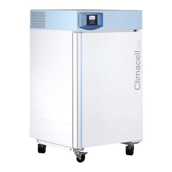
Instructions for use DEVICE DESCRIPTION 111, 222 GENERAL VIEW OF CLIMACELL EVO Fig. 1 CLIMACELL EVO_np_en_1401_mmm_V1.01... -
Page 8: General View Of Climacell Evo 404, 707
Instructions for use 404, 707 GENERAL VIEW OF CLIMACELL EVO Fig. 2 CLIMACELL EVO_np_en_1401_mmm_V1.01... -
Page 9: Communication Panel
Instructions for use COMMUNICATION PANEL Fig. 3 Standard version Network push button Pump connector Control touch panel Input of steam from steam generator Plastic cover of control panel Waste vessel with pump Condenser Waste water discharge Compressor Water inlet from reservoir Cooling tube evaporator - Distilled water reservoir 6a - cooling,... -
Page 10: Control Panel
Instructions for use CONTROL PANEL Fig. 4 (1) Control touch panel (2) SD card (3) Indication LED USEFUL SPACE Useful space is displayed in Fig. 5. In the space delimited with thick lines in the fi gure there are fulfi lled (in connection with standard DIN 12 880) the temperature variations as specifi... -
Page 11: Technical Data I
Instructions for use TECHNICAL DATA I GENERAL DATA Name CLIMACELL E 111 / 111-c 222 / 222-c 404 / 404-c 707 / 707-c 1212 / 1212-c Inner space of the chamber, Volume approx. litre 1408 stainless steel DIN 1.4301 Width 3x540 (1905) (AISI 304) Height... -
Page 12: Ommunication Interface
Instructions for use Heat losses at 37 °C ca W Complete device noise level 50/56 56/58 Operation conditions Let the installed device stand still in operation position for 2 hours before its fi rst put into operation! Ambient temperature °C +5 up to +40 Max. -
Page 13: Bushings With Diameter 25, 50, 100
Instructions for use BUSHINGS WITH DIAMETER COMMUNICATION SW 50, 100 WARMCOMM FOR PC WITH WINDOWS Standard placement of bushings can be found approximately in the centre of the side (left or right) wall The program WarmComm is designed for recording of the of the chamber. -
Page 14: Exposition Lighting In Doors
Instructions for use 6.13 CHAMBER DE CONTAMINATION – „0“). The connection socket – fork must be appropriately tightened so as not to decrease the declared degree of protection (IP 67). After disconnection of the fork and the The chamber is heated to 160 °C and the temperature is socket carefully screw the protection covers on the socket kept for specifi... -
Page 15: Putting The Device Into Operation
Instructions for use PUTTING THE The devices are not designed for environment with risk of fl ammable or explosive substances DEVICE INTO (e.g. anaesthetics). OPERATION If the device is used with CO , it is necessary to protect the premises in case of excessive gas UNPACKING AND CONTROL leakage (well ventilated room, sensors of CO with alarm, etc.). -
Page 16: Device Placement
Instructions for use It is not possible to start decontamination in devices with a window in the door. The temperature and RH regulation is negatively affected by reduction of fan speed, exposition lighting and measuring of CO . There do not apply the values from chapter 11.1. -
Page 17: Connection To Distribution Network
Instructions for use BASIC MENU (10) (11) (12) (13) Fig. 11 d) Pull the hose from the generator (P1) through the bushing in the cask and apply the submersible pump (2), (P2). Then tighten the bushing in such a way so as the hose (P3) is sealed. -
Page 18: National Environment
Instructions for use 8.3.2 USER ADMINISTRATION → The device controls can be accessed in two different modes: ● Without user administration See 8.3.2.1. ● With advanced user administration See 8.3.2.2. 8.3.2.1 WITHOUT USER ADMINISTRATION MODE (10) (11) (12) This mode is the factory default setting. The user has access to all the device’s menus with the exception of Fig. -
Page 19: Activating Advanced User Administration
Instructions for use Operator-type users may be placed into four groups, Select advanced user administration after logging in in the depending on their rights, see 8.3.2.2.1. The fi eld (7), Fig. 12, displays the operator name. → user menu : ●... -
Page 20: Changing User Password
Instructions for use 8.3.2.2.2 CHANGING USER PASSWORD User editing. See (4), Fig.16. Under the icon the user (administrator or operator) an change his access password. Fig. 18 (1) Button for defi ning administrator password. The fi rst button in the list is reserved for the administrator. -
Page 21: History Of Faults
Instructions for use ● The LED signal light fl ashes (lights up) red. 8.3.3.2 HISTORY OF FAULTS → After fault elimination and after confi rmation by push button the fault is transferred to the history of faults (Fig. 22). You can display the history of faults by pressing in the menu for device setting (Fig. -
Page 22: Device Maintenance Menu
Instructions for use the program is running. Defrosting is ctivated in the device maintenance menu. Warning: In case of single defrosting the temperature in the chamber of the device increases to 50 °C, so take the tested samples out of the incubator so as to avoid their damage. -
Page 23: Drying
Instructions for use Notes: ● In the course of drying, the fan revolutions are set to Decontamination is not possible in some versions of the 100 % and temperature in the chamber is kept around device as the high temperature could damage some 40 °C. -
Page 24: Communication - Activation
Instructions for use (1) Communication interface for WarmComm4 (2) Identifi cation number of the device The number allows distinguishing of individual devices in cases when a user uses several CLIMACELL EVO devices at once. Displaying the device identifi cation number on the device display - see 8.4.7. -
Page 25: E- Mail Account Activation
Instructions for use (1) Password Index. server providing e-mail services. Contact your system The user may have as many as four passwords administrator to create an account, respectively use for access to the access point. The password services of any of public e-mail service providers (www. index defi... -
Page 26: Print
Instructions for use Fig. 36 (1) IP address of Wifi . Fig. 38 8.3.8 PRINT Fig. 37 The menu is displayed using the icon (Fig. 13). (1) Icon for faults displaying. Note: We recommend use of the printer DPT6333, see 6.16. Fig. -
Page 27: Protocol Printing
Instructions for use 8.3.9 BACKUP (1) Communication interface selection. (2) Data format supported by the printer The data format is set in the technical specifi cation of the printer. For the printer DPT6333 select „DPT“. (3) Options for printing. CLIMACELL EVO allows performance of backup of some Automatic printing –... -
Page 28: Thernet Setting
Instructions for use The settings described in this chapter suppose that the After editing, you must switch the device on and device is equipped with communication module, see off using the push button ON/OFF! 6.15. (8) Ethernet setting. (9) Wifi setting. (10) E-mail setting. -
Page 29: Touch Panel Correction
Instructions for use 8.3.10.1.3 MAIL SETTING Fig. 44 (1) Current value of calibration in pixels for axis x Fig. 43 (1) Sending and y Switched off / via Wifi / via Ethernet. (2) Push buttons for movement of active fi eld of touch (2) SMTP. -
Page 30: Rack
Instructions for use 8.3.10.4 RACK . is issued. A service call-out is required to restore full capacity. → Rack This service menu serves for entering the value of VIS and UV light intensity under individual light racks in case that the device is not equipped with sensors for light intensity measuring (optional equipment, see 6.11). -
Page 31: Overview Of Inputs And Outputs
Instructions for use 8.3.10.6.2 DIGITAL INPUTS AND OUTPUTS (4) File name. 8 characters as a maximum. (5) Number of exported records. 8.3.10.6 OVERVIEW OF INPUTS AND OUTPUTS This menu provides information on statuses of all the sensors and action elements within the whole device. It serves mainly for service purposes and it may be used in remote diagnostics of the device. -
Page 32: Programs
Instructions for use Fig. 51 Fig. 52 (1) Test name (1) Push buttons for relevant program selection. (2) Total test time. (3) Current temperature. 8.4.2 DEFINITION OF PROGRAM (4) Current test phase. (5) Current test phase time. In the end of the test, this position will continue to display time of phase „3“... -
Page 33: Program Configuration
Instructions for use Exposition – the segment is terminated in case that there was reached the required exposition of visible light (klx.h) or UV radiation (mW.h/cm The exposition selection is possible only at devices with exposition lighting and sensors for measuring the light intensity (see 6.10 and 6.11). -
Page 34: Segment Settings
Instructions for use 8.4.4 SEGMENT SETTINGS space thermo homogeneity in the chamber of the incubator. The next step is to set the program sub-segments. Fig. 55 For optimal regulation we recommend setting to shows the example of temperature regulation program P1, 100 %. -
Page 35: Alarms
Instructions for use Note: (1) Monitored variable A condition for fi nishing a program in programs with light Alarms may be set for temperature, humidity and exposition is the selected exposition (see Fig. 53). concentration In case of the device not to be equipped with sensors for (2) Setting monitored limits light intensity measuring, there must be set the value of See fi... -
Page 36: Program Start Menu
Instructions for use 8.4.6 (23) PROGRAM START MENU After all the segments setting and program saving we (22) reach the menu where it is possible to start the program respectively to further adjust it. (21) (20) (19) (18) (10) (11) (12) (13) (14) (15) (16) (17) Fig. -
Page 37: Running Program Graph
Instructions for use d – it has the meaning of the number of passed (1) Options for time displaying days „BY END“ – it displays the time remaining by the (19) End of displayed time interval. end of selected part of the program. (20) Movement upwards / downwards. -
Page 38: Door Opening
Instructions for use Fig. 64 (1) Automatic start date Fig. 66 (2) Automatic start time (3) Segment, from which the program is to start. (4) Cycle, from which the program is to start. (5) Time of start within the selected segment. (6) Start confi... -
Page 39: Door Blocking In The Mode Of Advanced Users Administration
Instructions for use Fig. 68 Fig. 69 (1) Door blocking icon Blocking is activated (deactivated) by touch. (1) Entry to program editing. After fi nishing the editing, the user is asked whether he 8.4.7.5.2 wants to interrupt the currently running program and save DOOR BLOCKING IN THE MODE OF changes. -
Page 40: Power Supply Outage
Instructions for use 8.4.7.7 POWER SUPPLY OUTAGE A relevant graph is displayed after selection of an item from the list: In case of power supply network outage in the course of the program ruin, all the running program settings are preserved and even the real time clock goes on in the course of the outage. -
Page 41: Ystem Information
Instructions for use (1) Memory medium selection USB fl ash disk is possible only with devices with communication module, see 6.15. (2) Record format. Format CSV is suitable for export to Microsoft Excel. (3) Export range. It is possible to export compete record or a part of (4) File name. -
Page 42: List Of Error Messages
Instructions for use LIST OF ERROR MESSAGES Number Location Name Relevance Cause Way of elimination System version error Hard There is a set of fi rmware in the device Contact authorised service which is mutually incompatible Faulty program defi nition. Hard Started program is damaged or the Repeat the program editing and save program version is incompatible with... - Page 43 Instructions for use Humidity sensor Hard Faulty sensor or source +24 V. Contact authorised service interrupted. Humidity sensor short- Hard Faulty sensor or source +24 V. Contact authorised service circuited. Flexible Pt 1 interrupted. Soft Faulty temperature sensor. Contact authorised service Flexible Pt 1 short- Soft Faulty temperature sensor.
-
Page 44: Device Maintenance
Instructions for use Internal error Slv 203 Hard Fault of fuzzy regulator of RH (this Switch the device on and off using the should never occur) network switch. Contact authorised service in case that the problem persists. Comm Internal error Com 400 Soft Fault of reading EEPROM Com Switch the device on and off using the... -
Page 45: Door Sealing Replacement
Instructions for use 10.2 10.3 DOOR SEALING REPLACEMENT DOOR ADJUSTMENT (1) Outer door sealing (m. No. 0672719 size 111 - 707) The glass door has a fi xed position and it can be only turned around its axis or get out of hinges. The outer sheet door is adjustable in all the four positions (see Fig. -
Page 46: Accumulation Of Condensed Water Steam
Instructions for use 10.4 ACCUMULATION OF CONDENSED WATER STEAM When the incubator is operated under specifi c conditions (high humidity), condensate may accumulate in the space between the glass door and outer door. The condensate is collected below the glass door and it is taken away to the waste vessel placed below the device. -
Page 47: Steam Generator
Instructions for use In case of contaminated material leakage to the chamber of the device, the user is responsible for appropriate performance of decontamination of all and any contaminated surfaces with suitable and approved disinfection means. Before using any other method of cleaning or decontamination than the methods recommended by us it is purposeful for the user to check at the manufacturer that the method could not do any harm to the device. -
Page 48: Technical Data Ii
Instructions for use TECHNICAL DATA II 11.1 OPERATION DATA Type 111 / 111-c 222 / 222-c 404 / 404-c 707 / 707-c 1212 / 1212-c Operation temperature *) from 0 °C to °C 100 (decontamination 160 °C) from -20 °C to °C 100 (decontamination 160 °C) Temperature precision... -
Page 49: Racks With Exposition Lighting
Instructions for use 11.2 RACKS WITH EXPOSITION LIGHTING FLUORESCENT LAMPS Name CLIMACELL E 111 / 111-c 222 / 222-c 404 / 404-c 707 / 707-c 1212 / 1212-c Width x depth x height of rack 539x350x90 539x500x123 539x500x123 939x512x93 539x500x123 Number of fl... -
Page 50: Warranty And Service
Instructions for use WARRANTY AND WAY OF SERVICE LIQUIDATION The guarantee period is marked on the certifi cate of The package is made of wood, nails, cardboard, paper and warranty. plastics, which can be recycled as like as household waste. The warranty refers to manufacturing defects or material For European Union countries: defects on condition that:... - Page 52 Manufactured in the EU MMM Medcenter Einrichtungen GmbH Semmelweisstrasse 6 D-82152 Planegg Germany T. +49 89 89 92 26 20 F. +49 89 89 92 26 30 e-mail: medcenter@mmmgroup.com...
Need help?
Do you have a question about the CLIMACELL 111 and is the answer not in the manual?
Questions and answers
How do I enable the carboy water pump?