Table of Contents
Advertisement
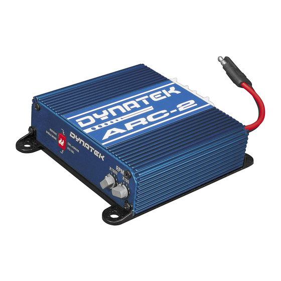
Asynchronous Restriking CDI – 2 channel
Specifications
Operating Voltage:
Operating Current:
Max Operating RPM:
Ambient Temp range:
Ignition inputs:
Ignition outputs:
Ignition output energy:
Ignition output Voltage:
WARNING: DO NOT INSTALL THIS ON A VEHICLE ALREADY EQUIPPED WITH A CAPACITIVE DISCHARGE IGNI-
NOTE : YOU MUST ALSO PURCHASE AN INSTALL KIT. THERE ARE MODEL SPECIFIC KITS FOR CERTAIN VE-
HICLES, OR GENERIC INSTALL KITS. FOR EASIEST INSTALL, USE A MODEL SPECIFIC KIT, AS THIS WILL HAVE
BEEN TESTED ON YOUR VEHICLE, AND INCLUDE BRACKETS, HARNESSES, SETUP INSTRUCTIONS, AND
OTHER ITEMS TO MAKE INSTALL AS TROUBLE FREE AS POSSIBLE. GENERIC KITS INCLUDE A STANDARD
HARNESS, AND MAY REQUIRE BRACKET FABRICATION, AS WELL AS SPLICING THE HARNESS INTO THE VE-
NOTE: SOME VEHICLES HAVE IGNITION COILS THAT ARE NOT COMPATIBLE WITH CDI STYLE IGNITIONS.
Dynatek 164 S. Valencia St. Glendora CA, 91741
8-20V
7A@10,000 RPM
18,000 RPM
Min: Below -40C
Max: +90 C
2, rising or falling edge selectable
2 independent channels capable of
asynchronous operation
189+ mJ per channel
500+ Volts
HICLES STOCK HARNESS.
Restrike window:
Max number of sparks
per sequence:
Launch limiter range:
Launch limiter input:
Timing Retard:
Timing Retard input:
Tach output:
Recommended power fuse:
Dimensions:
Weight:
TION.
2801211a
Parts List
ARC-2 module
Decals
Power Cable
Fuse
25 degrees, up to 3500 RPM
5
3000-11900 RPM
Single wire, ground to activate
10 degrees user activated
Single wire, ground to activate
0-12V square wave, 50% duty cycle,
Standard 4 cylinder configuration,
30A ATC Blade
4.1"x4.6"x1.5"
1.5 lbs
www.dynaonline.com
Installation Guide- 1
Advertisement
Table of Contents

Subscribe to Our Youtube Channel
Related Manuals for DYNATEK ARC-2


Summary of Contents for DYNATEK ARC-2
-
Page 1: Parts List
HARNESS, AND MAY REQUIRE BRACKET FABRICATION, AS WELL AS SPLICING THE HARNESS INTO THE VE- HICLES STOCK HARNESS. NOTE: SOME VEHICLES HAVE IGNITION COILS THAT ARE NOT COMPATIBLE WITH CDI STYLE IGNITIONS. Dynatek 164 S. Valencia St. Glendora CA, 91741 www.dynaonline.com Installation Guide- 1... -
Page 2: Pre-Installation
The ARC-2 ignition was designed with several key technologies that enable it to optimize your vehicles ignition system, and realizing the performance potential of your vehicles engine. The design features that help to do this were how the ARC-2 was named –... -
Page 3: Ignition Coils
With that much timing delay, multiple sparks are clearly not for power. The ARC-2 improves upon this by lowering the time it takes to get that second spark, using a proprietary technique called Intelligent Spark Profiling, or ISP. -
Page 4: Spark Plugs
2 choices. You can install the ARC-2 between the power transistor and coil, and set it up like a standard coil. Or you can remove the power transistor, and wire the ARC-2 directly to the ECU and coil, and set the ARC-2 up as if you were replacing a coil w/driver. -
Page 5: Standard Installation Procedure
2 cut wire ends as shown. Make sure the Coil Edge Select switch on the ARC-2 is set to the correct setting. Set the Launch Limiter RPM to Off. Plug in Power Harness, install fuse. Plug in Main Harness. - Page 6 Note: Perform all cuts and splices close to the coil. There should be NOTHING ELSE connected to the wires that go between the ARC-2 and coil (the white, blue, and black wires). Failure to follow this will likely damage anything else connected, and possibly damage the ARC-2 and coil as well.
- Page 7 Note: Perform all cuts and splices close to the coil. There should be NOTHING ELSE connected to the wires that go between the ARC-2 and coil (the white, blue, and black wires). Failure to follow this will likely damage anything else connected, and possibly damage the ARC-2 and coil as well.
- Page 8 Note: Perform all cuts and splices close to the coil. There should be NOTHING ELSE connected to the wires that go between the ARC-2 and coil (the white, blue, and black wires). Failure to follow this will likely damage anything else connected, and possibly damage the ARC-2 and coil as well.
- Page 9 DIP Switch and Rotary Switches There are 2 dip switches on the ARC-2 module, and 2 rotary switches. All switches are read at power up, and not read after- wards. This is for reliability in high vibration environments, and to ensure that settings can not be accidentally tampered with while the engine is running.
- Page 10 4 cylinder bikes with coil on plug. Vehicle specific harnesses will include a tach adaptor adapter to correct this, if it is needed for that application. If a tach adaptor is required on a custom application, contact Dynatek for a Universal Tach Adaptor kit. Dynatek 164 S.
Need help?
Do you have a question about the ARC-2 and is the answer not in the manual?
Questions and answers