
Related Manuals for Murphy POWERVIEW PV450

Summary of Contents for Murphy POWERVIEW PV450
- Page 1 PowerView ® Model PV450 Installation and Operation Manual 00-02-0732 2016-02-26 Section 78...
- Page 2 In order to consistently bring you the highest quality, full featured products, we reserve the right to change our specifications and designs at any time. The latest version of this manual can be found at www.fwmurphy.com. BEFORE BEGINNING INSTALLATION OF THIS MURPHY PRODUCT: •...
-
Page 3: Table Of Contents
Table of Contents Hardware Installation ......................... 1 Inspecting Package Contents ................... 1 Dash-Mounted Installation ....................1 Wiring Instructions ........................4 Single Engine ........................4 PVA Gages ........................... 5 NMEA Gages ........................6 Dual Engine Gages ......................7 USB Wiring ........................... 8 Analog Video ........................ - Page 4 (THIS PAGE INTENTIONALLY LEFT BLANK)
-
Page 5: Hardware Installation
NOTE: When using the paper template from the manual, please be aware that if you downloaded this document from the FW Murphy website, the pdf file may not automatically print to scale. When submitting the file for print, you will need to select “None”... - Page 6 Front Installation of Display 1. Place the back side of the display through the opening in the dash. 2. Use the 4 screws to line up the unit with the drilled holes. 3. Push the unit through the opening and screws through the drilled holes until the back of the case is flush.
- Page 7 Dimensions for Installation Section 78 00-02-0732 2016-02-26 - 3 -...
-
Page 8: Wiring Instructions
Wiring Instructions The following illustrations are examples of various typical quick-connect options for setup. Wiring harnesses are sold separately. WARNING: Failure to install the unit per the specified wiring diagrams may cause damage to the unit. DO NOT connect power to the video ground. Warranty is void for damage caused by incorrect wiring. -
Page 9: Pva Gages
PVA Gages WARNING: Failure to install the unit per the specified wiring diagrams may cause damage to the unit. DO NOT connect power to the video ground. Warranty is void for damage caused by incorrect wiring. Section 78 00-02-0732 2016-02-26 - 5 -... -
Page 10: Nmea Gages
NMEA Gages Section 78 00-02-0732 2016-02-26 - 6 -... -
Page 11: Dual Engine Gages
Dual Engine Gages NOTE: Port B and C connectors are keyed differently than Port A and D connectors to ensure proper connection. Section 78 00-02-0732 2016-02-26 - 7 -... -
Page 12: Usb Wiring
USB Wiring Section 78 00-02-0732 2016-02-26 - 8 -... -
Page 13: Analog Video
Analog Video WARNING: Failure to install the unit per the specified wiring diagrams may cause damage to the unit. DO NOT connect power to the video ground. Warranty is void for damage caused by incorrect wiring. Section 78 00-02-0732 2016-02-26 - 9 -... -
Page 14: No Video Wiring
No Video Wiring WARNING: Failure to install the unit per the specified wiring diagrams may cause damage to the unit. DO NOT connect power to the video ground. Warranty is void for damage caused by incorrect wiring. Section 78 00-02-0732 2016-02-26 - 10 -... -
Page 15: Pin Specifications For Deutsch Dt04-6P Style Connections
Pin Specifications for Deutsch DT04-6P Style Connections WARNING: Failure to install the unit per the specified wiring diagrams may cause damage to the unit. DO NOT connect power to the video ground. Warranty is void for damage caused by incorrect wiring. Signal Definitions •... -
Page 16: Pv450 Features And Operations
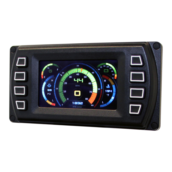
PV450 Features and Operations LCD Screen Display A color screen displays gauges, soft key commands, and fault messages, as well as menu options for setup and configuration. Soft Key Commands Columns of vertical commands may be located to the left and/or right of the display. They will change according to the options available for the screen being displayed. -
Page 17: Setting Up Your Pv450 Display For The First Time
The guidelines presented below are intended for setting up the PV450 display for the first time. Once the configuration is set up, there is no need to revisit or change any of the settings. NOTE: If you require assistance during the set up process, contact FW Murphy customer support at +1(918) 317-4100. - Page 18 Save key to save selected changes or the Restore Defaults key to return to the default settings. Section 78 00-02-0732 2016-02-26 - 14 -...
-
Page 19: Product Features
Product Features Power Up There are two options to connecting the PV450 display: • The battery and ignition inputs to display are both connect to the battery • The battery input is connected to the battery and the ignition input is connected to the ignition switch. -
Page 20: Gauge Display
Gauge Display The Gauge Display screen consists of several predefined layouts that contain combinations of analog gauges, straight bar gauges, or digital (text) readouts. These screens are displayed upon startup. To scroll through the various gauge screens, press the Prev and Next soft keys. This can be repeated until all screens have been viewed. - Page 21 Day/Night - Allows you to toggle the display screen between Day View and Night View. NOTE: This feature can also be changed in the “User Settings” section of this manual. Video – When enabled, displays either full screen video or partial video within a window on the gauge display.
-
Page 22: Engine Diagnostics
Engine Diagnostics Choosing Engine Diagnostics from the Menu, the display will query the engine(s) ECU and provide feedback on any diagnostic codes that have been activated and stored in the ECU for service needs. The Engine Diagnostics option displays faults based on engine or auxiliary source. The following is a list of field definitions contained on the Engine Diagnostics screen: •... -
Page 23: Fault Code Popups
Fault Code Popups A fault condition will trigger a popup dialog box on the screen describing the nature of the fault. Corresponding red or amber fault lights on the corners of the unit are also activated to indicate the severity of the fault. The following screens are examples of warning and shutdown fault code popups. -
Page 24: User Settings
User Settings User Settings provides options to specify viewing preferences for the PV450 Display. Pressing yellow Up and Down arrows navigates through the options. To change an option, press the corresponding soft key button next to the desired soft key command. Ambient Light Night and Day options are provided for ambient lighting. - Page 25 Brightness You can set the brightness control by using the soft keys to change the settings in +5% increments until the desired brightness is achieved. NOTE: Brightness level will change with ambient light setting. Two brightness levels are saved; one for day and one for night. Units Select how units are displayed by using the soft keys to select from the following: •...
- Page 26 Language This option allows you to select the language that will be displayed on the PV450. Available languages include English, French, Spanish, German, Italian, and Chinese. Languages are selected from the soft keys. Press the Down arrow to view additional languages. Additional languages include: Russian, Czech, Japanese, and Brazilian Portuguese.
-
Page 27: Home Screen
The Screen Setup screen also provides the user the ability to turn the screens ON or OFF by pressing the Enable/Disable soft key. If a screen is turned OFF, it will not show up when Gauge Display is activated. Home Screen The Home Screen will be the first screen shown when Gauge Display is selected from the User Setting menu. -
Page 28: Utilities
Restore Defaults Restore Defaults sets the display to the original factory settings. During troubleshooting, this can be used as a last resort to completely reset the display to a known state. To restore the default user settings, press Restore Defaults. The following confirmation screen is displayed. -
Page 29: System Settings
• Service Engine – Default interval 125.0 Hrs. • Service Machine – Default interval 150.0 Hrs. NOTE: The PV450 is Tier 4 compliant. If there are any questions on the Murphy Standard Configuration please contact Enovation Controls Technical Services at: (918) 317-1113 Section 78... -
Page 30: Specifications
Specifications Electrical Display Bonded 4.3” color transmissive TFT LCD Resolution WQVGA, 480 x 272 pixels, 16-bit color Aspect Ratio 16:9 Orientation Landscape or portrait Backlighting LED, 500-650 cd/m2 (30,000 hr lifetime) Microprocessor Freescale iMX35, 32bit, 532 MHz Operating System QNX Real Time Flash Memory 256 MB (expandable to 8GB) 128 Mb DDR2 SDRAM... -
Page 31: Addendum
Addendum How to Install a Configuration from a USB Drive for the PV450 1. READ ALL INSTRUCTIONS BEFORE CONTINUING! 2. Power OFF the display unit. 3. Insert USB drive with the configuration file into USB port. 4. Press and hold the top left button (continue to hold). 5. - Page 32 NOTES Section 78 00-02-0732 2015-05-19 - 28 -...
- Page 37 NOTES...
- Page 38 NOTES...
- Page 39 NOTES...
Need help?
Do you have a question about the POWERVIEW PV450 and is the answer not in the manual?
Questions and answers