Advertisement
code 9IS43049
GB
rel. 6/06
USER INTERFACE
The user has a display and four buttons
for controlling instrument status and pro-
gramming.
BUTTONS AND MENUS ACCESSING
UP Button
Scrolls through the menu items
Increases the values
DOWN button
Scrolls through the menu items
Decreases the values
fnc button
ESC function (quit)
fnc
Set point button
1-Accesses Machine Status Menu
(ACTIVE ALARMS, PROBE READ-
ING) and related labels/values;
set
1-Accesses Programming Menu
(PARAMETERS, COPY C ARD (LX
models)) and related labels/val-
ues;
3-Confirms commands
AND USING MENUS
The resources are arranged in a menu that
can be accessed by pressing and quickly
releasing the "set" button (Machine Status
menu) or holding down the "set" button
for more than 5 seconds (Programming
menu). To access the contents of each
folder indicated by the relevant label, just
press the "set" button once. You can now
scroll through the contents of each folder,
modify it or use its functions. If you do
not use the keyboard for over 15 seconds
(time-out) or if you press the "fnc" button
once, the last value shown on the display
is confirmed and you return to the previ-
ous screen mask.
MACHINE STATUS MENU
(See Machine Status Menu Diagram)
To access the Machine Status menu, press
the "set" button and quickly release it
(The "SP1" label appears.
V/I
V/I
(If alarms are active, with the exception of
faulty probes/probe errors, the "AL" label
appears). By using the "UP" and "DOWN"
buttons you can scroll through the other
folders in the menu: the folders are indi-
cated below in the order they appear:
-AL: alarm folder
LX
MODELS
LX
MODELS
NOTE: The AL folder appears if high or
low temperature alarms are present.
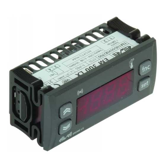
EM300(LX)
electronic digital indicator
Alarm (IF PRESENT)
•ON for active alarm;
•blinking for silenced
alarm that is still present
L L E E D D S S A A N N D D
K K E E Y Y P P A A D D
ALARM PRESENT?
If an alarm condition exists when the
"Machine Status" menu is accessed, the
"AL" folder label appears with the alarm
codes. (see section on "Diagnostics").
HOW TO LOCK THE KEYBOARD
Keyboard operating can be locked by pro-
gramming the "Loc" parameter (see folder
with "diS" table). If the keyboard is locked
you can only access the Programming
MENU (see) Functions CANNOT be activat-
ed with buttons (to silence alarms, for
example).
TELEVIS SYSTEM (LX MODELS ONLY)
The Televis remote control systems can be
connected using the TTL serial port.
The TTL- RS 485 interface module must be
used:
• 130 or 150 BUS ADAPTER.
• 350 BUS ADAPTER for EM300(LX) with
V/I. Pt100/TC input.
To configure the instrument to do this, you
MODELS
ONL
Y)
MODELS
ONL
Y)
need to access the folder with the "Add"
label and use the "dEA" and "FAA" para-
meters.
ONL
Y
ONL
Y
press and release
(single press)
decimal point:
associated with displaying
decimal point
•ON if enabled-decimal
point present (see ndt
parameter);
•OFF if disabled-decimal
point NOT present (see
ndt parameter);
MACHINE STATUS MENU DIAGRAM
set
AL
for NTC/PTC
or Pt100-TC
input
for V/I input
(current-
voltage std
signals)
DIAGRAM
set
set
press for 5 sec
PA1≠0
ONLY MODELS LX
rE1
input VI
set
level 1 par
AL
ONLY MODELS LX
set
level 1 par
Add
set
level 1 par
dIS
set
level 1 par
CnF
ONLY MODELS LX
set
level 1 par
Fpr
level 1
PC with
Televis package
only use 350 Bus Adapter for model with V/I,
Pt100/TC input
set
alarms
scroll alarms
bar for
V/I input
(pressure)
%RH for
V/I input
(humidity)
set PA1 value
scroll
parameters
change
par value
L
230V
N
if alarm(s)
present
Advertisement

Related Manuals for Eliwell EM300

Summary of Contents for Eliwell EM300
-
Page 1: User Interface
• 130 or 150 BUS ADAPTER. PC with Televis package MACHINE STATUS MENU • 350 BUS ADAPTER for EM300(LX) with (See Machine Status Menu Diagram) V/I. Pt100/TC input. To access the Machine Status menu, press the “set” button and quickly release it (The “SP1”... - Page 2 •higher than or equal to LAL/LA1 + AFd MAXIMUM AND MINIMUM TEMPERATURE ALARM If an alarm condition occurs and alarm exclu- sion times are not in progress (see alarm exclu- Max/Min. Alarm sion parameters), the fixed alarm icon comes Diagram (minimum and maximum temperature) LAL/LA1 HAL/HA1 EM300(LX)
- Page 3 GENERAL TECHNICAL EM300(LX) TECHNICAL DATA ELECTRICAL DATA WITH PTC/NTC INPUT WIRING Front protection: IP65. Casing: PC+ABS Warning! Always switch off machine Display range: UL94 V-0 resin plastic body, polycarbonate before working on electrical connec- • NTC probe: –50.0…110.0°C (–58…230°F); front, thermoplastic resin buttons.
- Page 4 ** VALUE column: to be compiled manually with any custom settings (if different from default value). DISCLAIMER (°) The mathematical conversion for temperature RESPONSIBILITY AND RESIDUAL RISKS Eliwell & Controlli s.r.l. shall not be liable for any dam- This document is exclusive property of Eliwell & is °F=(9/5)* °C+32. For example: 32°F=0°C; ages deriving from: Controlli s.r.l.
- Page 5 PARAMETER TABLE FOR EM300(LX) with V/I & Pt100-TC input R R A A N N G G E E ( ( P P t t 1 1 0 0 0 0 ) ) PARAMETER DESCRIPTION R R A A N N G G E E ( ( V V / / I I ) )
- Page 6 V Models * Check probe connection polarity. 3 - 4 - 5 Voltage input (3=GND; 4=signal; 5=+12V)* EWHS 300/310 3 wires Power Supply from EM300(LX) EWHS 280 2 wires Power Supply from EM300(LX) 3 4 5 3 4 5 Probe...