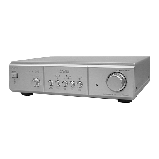
Sony TA-P9000ES Service Manual
Multichannel pre amplifier
Hide thumbs
Also See for TA-P9000ES:
- Operating instructions manual (32 pages) ,
- Dimensions (1 page) ,
- Technical background (38 pages)

Related Manuals for Sony TA-P9000ES


Summary of Contents for Sony TA-P9000ES
-
Page 1: Service Manual
TA-P9000ES SERVICE MANUAL US Model Canadian Model AEP Model Photo: gold type SPECIFICATIONS MULTICHANNEL PRE AMPLIFIER MICROFILM... -
Page 2: Table Of Contents
DES PIÈCES SONT CRITIQUES POUR LA SÉCURITÉ SONY PARTS WHOSE PART NUMBERS APPEAR AS DE FONCTIONNEMENT. NE REMPLACER CES COM- POSANTS QUE PAR DES PIÈCES SONY DONT LES SHOWN IN THIS MANUAL OR IN SUPPLEMENTS PUB- LISHED BY SONY. NUMÉROS SONT DONNÉS DANS CE MANUEL OU DANS LES SUPPLÉMENTS PUBLIÉS PAR SONY. -
Page 3: Servicing Notes
Check the antenna terminals, metal trim, “metallized” knobs, screws, and all other exposed metal parts for AC leakage. TA-P9000ES MODEL NO. Check leakage as described below. MULTI CHANNEL PRE AMPLIFIER... -
Page 4: General
SECTION 2 This section is extracted from instruction manual. GENERAL – 4 –... -
Page 5: Disassembly
SECTION 3 DISASSEMBLY Note: Follow the disassembly procedure in the numerical order given. CASE 2 two screws 3 case (BV3 × 8 CU) 1 two flat head screws 1 two flat head screws FRONT PANEL SECTION 1 Remove ten connectors. CN4, 101, 103, 114, 116, 117, 122, 124, 138, 142 8 front bracket... - Page 6 MAIN BOARD 1 Remove ten connectors. CN101, 103, 114, 116, 117 124, 129, 138, 139, 142 2 three screws (BV3 × 8 CU) 2 two screws (BV3 × 8 CU) 3 Remove the MAIN board in direction of arrow A . 2 seven screws (BV3 ×...
-
Page 7: Diagrams
SECTION 4 DIAGRAMS 4-1. NOTE FOR PRINTED WIRING BOARDS AND SCHEMATIC DIAGRAMS Note on Printed Wiring Board: Note on Schematic Diagram: • X : parts extracted from the component side. • All capacitors are in µF unless otherwise noted. pF: µµF •... -
Page 8: Master Volume Board
• Circuit Boards Location AC board POWER board LED board MAIN board AC SW board EYEBALL board MASTER VOLUME board CONTROL board SUB VOLUME board VOL LED board MUT board • Semiconductor Location Ref. No. Location Ref. No. Location Ref. No. Location Ref. - Page 9 TA-P9000ES 4-2. PRINTED WIRING BOARDS – MAIN Board/SUB VOLUME Board/MASTER VOLUME Board – • See page 8 for Circuit Boards Location. (Page 10) (Page 10) (Page 10) (Page 9) (Page 9) (Page (Page 9) (Page 9) (Page 15) (Page 16)
-
Page 10: Schematic Diagram - Main Board (1/2)/Sub Volume Board/Master Volume Board
TA-P9000ES 4-3. SCHEMATIC DIAGRAM – MAIN Board (1/2)/SUB VOLUME Board/MASTER VOLUME Board – (Page (Page 17) (Page (Page 21) (Page 21) (Page 18) – 11 – – 12 –... -
Page 11: Schematic Diagram - Main Board (2/2)
TA-P9000ES 4-4. SCHEMATIC DIAGRAM – MAIN Board (2/2) – (Page (Page 17) – 13 – – 14 –... -
Page 12: Printed Wiring Boards – Panel Section
TA-P9000ES 4-5. PRINTED WIRING BOARDS – PANEL Section – • See page 8 for Circuit Boards Location. (Page 9) • Semiconductor Location Ref. No. Location D801 (Page 10) D802 D803 D804 D805 D806 D807 D808 IC801 IC802 (Page 9) IC803... -
Page 13: Schematic Diagram – Panel Section
TA-P9000ES 4-6. SCHEMATIC DIAGRAM – PANEL Section – • See page 22 for Waveform. • See page 22 for IC Block Diagram. (Page 11) (Page 14) (Page 11) (Page 21) (Page 11) – 17 – – 18 –... -
Page 14: Printed Wiring Boards – Power Section
TA-P9000ES 4-7. PRINTED WIRING BOARDS – POWER Section – • See page 8 for Circuit Boards Location. (Page 20) (Page 19) (Page 15) (Page 10) (Page 9) – 19 – – 20 –... -
Page 15: Schematic Diagram - Power Section
TA-P9000ES 4-8. SCHEMATIC DIAGRAM – POWER Section – (Page 11) (Page 11) (Page 17) The components identified by mark ! or dotted Les composants identifiés par une marque ! sont line with mark ! are critical for safety. critiques pour la sécurité. Ne les remplacer que Replace only with part number specified. - Page 16 • IC Block Diagram – CONTROL Board – IC803 BA6208 MOTOR SWITCH DRIVE MOTOR SWITCH DRIVE • Waveform – CONTROL Board – 1 IC801 @º (X-OUT) 3.8 Vp-p 8 MHz – 22 –...
-
Page 17: Ic Pin Function Description
4-9. IC PIN FUNCTION DESCRIPTION • CONTROL BOARD IC801 TMP87C846N-4D22 (SYSTEM CONTROLLER) Pin No. Pin Name Description Relay drive signal output for the +6 dB gain control (for CENTER input signal) C6DBUP “H”: +6 dB on Relay drive signal output for the +12 dB gain control (for CENTER input signal) C12DBUP “H”: +12 dB on R6DBUP... -
Page 18: Exploded Views
SECTION 5 EXPLODED VIEWS NOTE: • -XX and -X mean standardized parts, so they • Items marked “*” are not stocked since they The components identified by mark ! or dotted line with mark are seldom required for routine service. Some may have some difference from the original ! are critical for safety. - Page 19 4-218-470-01 PANEL, FRONT (GOLD) 4-975-105-31 WINDOW, RAY CATCHER (GOLD) 4-218-470-11 PANEL, FRONT (BLACK) 4-219-621-21 PLATE (P), LIGHT INTERCEPTION 4-942-568-41 EMBLEM (NO.5), SONY (for BLACK) 4-211-465-11 ESCUTCHEON (LED) (GOLD) 4-218-464-01 PANEL, SIDE (GOLD) 4-211-465-21 ESCUTCHEON (LED) (BLACK) 4-218-464-11 PANEL, SIDE (BLACK)
- Page 20 (3) CHASSIS SECTION supplied supplied Canadian CNJ1 supplied CNJ1 supplied supplied supplied supplied supplied supplied supplied with S801 supplied with RV101, 103 - 106 supplied supplied supplied with RV107 The components identified by Les composants identifiés par une mark ! or dotted line with marque ! sont critiques pour la mark ! are critical for safety.
-
Page 21: Electrical Parts List
AC SW SECTION 6 ELECTRICAL PARTS LIST CONTROL NOTE: • Due to standardization, replacements in the • Items marked “*” are not stocked since they The components identified by mark ! or dotted line with mark parts list may be different from the parts speci- are seldom required for routine service. - Page 22 CONTROL EYEBALL MAIN Ref. No. Part No. Description Remark Ref. No. Part No. Description Remark R832 1-216-065-00 RES, CHIP 4.7K 1/10W * CN137 1-568-955-11 PIN, CONNECTOR 6P R833 1-216-065-00 RES, CHIP 4.7K 1/10W R834 1-216-065-00 RES, CHIP 4.7K 1/10W < DIODE > R838 1-216-049-11 RES, CHIP 1/10W...
- Page 23 MAIN Ref. No. Part No. Description Remark Ref. No. Part No. Description Remark C203 1-125-842-11 FILM C204 1-119-830-11 ELECT 330uF C501 1-115-339-11 CERAMIC CHIP 0.1uF C205 1-119-830-11 ELECT 330uF C502 1-106-343-00 MYLAR 1000PF 200V C503 1-115-339-11 CERAMIC CHIP 0.1uF C206 1-136-810-11 FILM 220PF 100V...
- Page 24 MAIN Ref. No. Part No. Description Remark Ref. No. Part No. Description Remark D306 8-719-800-76 DIODE 1SS226 Q211 8-729-018-59 TRANSISTOR 2SB1375-LC Q251 8-729-023-11 FET 2SK2145GTE85L D307 8-719-801-78 DIODE 1SS184 Q252 8-729-230-49 TRANSISTOR 2SC2712-YG D308 8-719-801-78 DIODE 1SS184 Q253 8-729-216-22 TRANSISTOR 2SA1162-G D351 8-719-025-25 DIODE 02CZ3.6-TE85L Q254...
- Page 25 MAIN Ref. No. Part No. Description Remark Ref. No. Part No. Description Remark Q503 8-729-216-22 TRANSISTOR 2SA1162-G R216 1-259-983-11 CARBON MELF 1/8W Q504 8-729-421-22 TRANSISTOR UN2211 R217 1-259-980-11 CARBON MELF 1/8W R218 1-259-980-11 CARBON MELF 1/8W Q505 8-729-216-22 TRANSISTOR 2SA1162-G Q506 8-729-421-22 TRANSISTOR UN2211 R219...
- Page 26 MAIN Ref. No. Part No. Description Remark Ref. No. Part No. Description Remark R503 1-216-065-00 RES, CHIP 4.7K 1/10W R362 1-260-002-11 CARBON MELF 3.3K 1/8W R504 1-216-025-00 RES, CHIP 1/10W R363 1-260-010-11 CARBON MELF 1/8W R505 1-216-079-00 METAL CHIP 1/10W R364 1-259-987-11 CARBON MELF 1/8W...
- Page 27 MAIN MASTER VOLUME POWER SUB VOLUME VOL LED Ref. No. Part No. Description Remark Ref. No. Part No. Description Remark RY112 1-755-295-11 RELAY RY113 1-755-295-11 RELAY 1-673-059-11 POWER BOARD RY301 1-755-295-11 RELAY ************ RY302 1-755-295-11 RELAY < CAPACITOR > RY351 1-755-295-11 RELAY RY352 1-755-295-11 RELAY...
- Page 28 TA-P9000ES Ref. No. Part No. Description Remark Ref. No. Part No. Description Remark MISCELLANEOUS ************** ! CNJ1 1-559-479-11 CORD, POWER (US, Canadian) ! CNJ1 1-575-953-11 CORD, POWER (AEP) ! T2 1-433-651-11 TRANSFORMER, POWER (US, Canadian) ! T2 1-433-652-11 TRANSFORMER, POWER (AEP) ************************************************************ ACCESSORIES &...
Need help?
Do you have a question about the TA-P9000ES and is the answer not in the manual?
Questions and answers