Uponor Smatrix Wave Installation And Operation Manual
Management system for underfloor heating and cooling installations
Hide thumbs
Also See for Smatrix Wave:
- Installation and operation manual (132 pages) ,
- Quick manual (224 pages) ,
- Quick manual (8 pages)

Related Manuals for Uponor Smatrix Wave


Summary of Contents for Uponor Smatrix Wave
- Page 1 Uponor Smatrix Wave/Wave PLUS U K I N S TA L L AT I O N A N D O P E R AT I O N M A N U A L 03 | 2015...
-
Page 2: Table Of Contents
Replace batteries ............71 6.10 Register system devices ..........42 13.9 Factory reset ............71 Install Uponor Smatrix Wave timer ....44 Operate Uponor Smatrix Wave PLUS interface .72 Placement of timer ..........44 14.1 Touch screen ............72 Label timer .............44 14.2 Home screen ............72 Insert batteries ............44... - Page 3 Maintenance ............84 15.1 Manual preventive maintenance ......84 15.2 Automatic preventive maintenance ......84 15.3 Corrective maintenance ..........84 15.4 Controller LEDs............84 15.5 Restore from backup (Wave PLUS only) ....85 Troubleshooting ..........86 16.1 Troubleshooting after installation ......87 16.2 Digital thermostats T-166, T-167 and T-168 alarms/problems .............88 16.3 Analogue thermostats T-163 and T-165...
-
Page 4: Copyright And Disclaimer
Modification or use of any of the contents of the or obligation. The manual is provided “as is” without manual for any other purpose is a violation of Uponor’s warranties of any kind, either expressed or implied. The copyright, trademark and other proprietary rights. -
Page 5: Dk 2 Preface
Risk of injury. Ignoring warnings can cause communication difficulties exist, Uponor recommends injury or damage components. relocating the antenna to a more optimal position, and not installing Uponor radio sources to close to each other, for solving exceptional problems. Caution! Ignoring cautions can cause malfunctions. -
Page 6: Uponor Smatrix Wave/Wave Plus
Uponor Smatrix Wave Thermostat Dig T-166 (digital controller by radio link. It is possible to mix the different thermostat T-166) types of Uponor Smatrix Wave thermostats in the same Uponor Smatrix Wave Thermostat Standard T-165 installation. (standard thermostat T-165) -
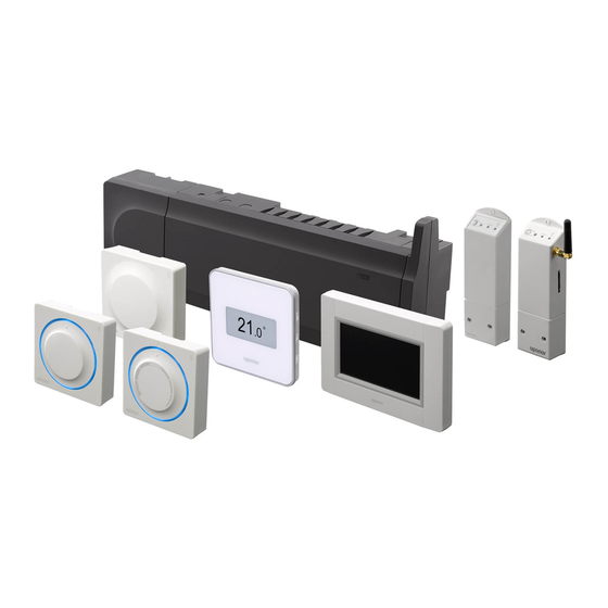
Page 7: Uponor Smatrix Wave/Wave Plus Components
• Integrated heat pump module (only available in selected countries, contact a local Uponor office for more information). U P O N O R S M AT R I X WAV E / WAV E P L U S · I N S TA L L AT I O N A N D O P E R AT I O N M A N U A L... - Page 8 Uponor Smatrix Wave Controller X-163 Main characteristics: • Integrated Dynamic Energy Management functions such as autobalancing. Item Description Uponor Smatrix Wave PLUS Controller X-165 • Electronic control of actuators. Uponor Smatrix Wave Controller X-163 • Connection of maximum eight actuators (24 V). Antenna •...
- Page 9 Interface (Wave PLUS only) • U@home connectivity (requires a remote module). Uponor Smatrix Wave PLUS Interface I-167 is a touch • Control of accessories (outputs etc). screen interface that can be connected through radio transmission to controller X-165. Components of the interface...
- Page 10 Uponor Smatrix Wave Thermostat Standard T-165 Uponor Smatrix Wave Thermostat Dig T-166 The thermostat temperature settings are adjusted using The thermostat shows the ambient or set temperature the dial. Maximum/minimum temperatures can only on the display. Temperature settings are adjusted using be set using an interface (Wave PLUS only).
- Page 11 Scheduling, pre-programmed and customizable schedules. Item Description • Lower indoor temperature on a room by room basis Uponor Smatrix Wave PLUS Thermostat D+RH T-167 with night set back. Wall bracket • Can be placed up to 30 meters away from the Stand controller.
- Page 12 Can be placed up to 30 meters away from the controller. Components of the thermostat: The illustration below shows the thermostat and its components. Item Description Uponor Smatrix Wave Thermostat Prog.+RH T-168 Wall bracket Stand Item Description Uponor Smatrix Wave Thermostat Public T-163 Batteries (AAA 1.5 V)
- Page 13 Timer Slave module Uponor Smatrix Wave Timer I-163 (Wave only) Uponor Smatrix Wave Slave Module M-160 The timer enables control of the system with The slave module adds six channels and actuator scheduling, Comfort/ECO settings, and Holiday mode outputs to an existing Uponor Smatrix Wave/Wave etc.
- Page 14 Relay module Uponor actuators Uponor actuators are mounted on top of the manifold Uponor Smatrix Wave Relay Module M-161 valves and is operated using either on/off signals or The relay module adds two extra output relays to the pulse width modulation (PWM) signals.
-
Page 15: Accessories
Accessories Functions Uponor offers a wide variety of accessories for use with Uponor Smatrix Wave/Wave PLUS is used to control an the standard portfolio. underfloor heating and/or cooling system in a house. The thermostats registered to the controller is used to control the actuators mounted on top of the manifold valves. - Page 16 Low hysteresis temperature Pump management (Wave PLUS with interface only) Uponor uses a low hysteresis temperature for best performance of the system. It is used for high control Each controller in a system has a pump relay, to which accuracy by deciding when to start and stop heating one pump can be connected.
- Page 17 (Wave PLUS with an interface only). MicroSD card (Wave PLUS only) Uponor Smatrix Wave PLUS uses a microSD card for cloning (settings), automatic backup (settings and thermostat registration data), manual restoration of backup, data logging (room data, controller data, system data and events) and upgrading software.
-
Page 18: Install Uponor Smatrix Wave/Wave Plus
Procedure Page Placement of interface First startup guide To determine where to best place the Uponor Smatrix Wave/Wave PLUS components, follow these guidelines: • Ensure that the controller can be installed close to the manifold pair. Note that each manifold pair must have its own controller. -
Page 19: Installation Example
See also the wiring diagram in the end of the manual. Caution! Only 24 V Uponor actuators are compatible with the controller. U P O N O R S M AT R I X WAV E / WAV E P L U S · I N S TA L L AT I O N A N D O P E R AT I O N M A N U A L... - Page 20 A connection example of Uponor Smatrix Wave/Wave • Floor temperature sensor. PLUS Controller (six channels) with an optional Uponor Smatrix Wave Slave Module (six extra channels) using Option B system devices (S) and thermostats (T) as shown in figure. •...
- Page 21 This requires one or more of the following: • Uponor Smatrix Wave PLUS Interface I-167 (Wave PLUS only) The interface allows individual programmed schedules for the rooms in the system. Any other devices with its own programmed schedules are overridden and its menus hidden.
-
Page 22: Install Uponor Smatrix Wave/Wave Plus Hr Controller
Install Uponor Smatrix Wave/Wave PLUS controller Placement of controller Attaching/detaching components The components can either snap on or off without the Refer to the installation preparation guidelines (see need of removing the covers (A), or by sliding them into section 4.2 Prepare for installation), and use the place when the covers are removed (B). -
Page 23: Install Controller Antenna
Install controller antenna Attach antenna to the wall The illustration below shows the antenna attached to The antenna can be attached to the right hand side of the wall with screws (A) or double-sided adhesive strips the controller or to the wall. If the controller is installed (B). -
Page 24: Connect The Slave Module (Optional)
Attach controller to the wall Screws and wall plugs The figure below shows controller mounting hole The controller is delivered in kits including screws, wall positions and how to attach it to the wall using screws plugs and a DIN rail. and wall plugs. -
Page 25: Connect Components To Controller
2. Remove the slave module. Use caution not to bend MicroSD card (Wave PLUS only) the connection pins. Power LED Uponor Smatrix Wave Slave Module M-160 (optional) LEDs for channels 07 – 12 Uponor Smatrix Wave Antenna A-165, RJ-45 connector... - Page 26 Connect thermostats to controller Thermostats are connected to the controller through wireless radio link. See also section 6 Uponor Smatrix Wave/Wave PLUS thermostats and sensors for installation of thermostats. Connect heating/cooling input to controller (optional)
- Page 27 1. Study the wiring diagram in the end of the manual, 4 = On. See section 6.4 Connect external sensor or inside the cover of the controller, to locate the to thermostat > Uponor Smatrix Wave Thermostat connector positions. Public T-163 for more information.
- Page 28 Relay module, system device channel 2. See 4 = Off. See section 6.4 Connect external sensor section 5.8 Register relay module M-161 for to thermostat > Uponor Smatrix Wave Thermostat installation of the relay module. Public T-163 for more information.
- Page 29 N O T E ! PUMP See the documentation from the circulation pump supplier as well as relevant Uponor wiring diagrams before connecting the pump. • The controller cannot supply power for the pump.
- Page 30 To connect a circulation pump to the controller: To connect a circulation pump to a relay module: The illustration below shows a circulation pump connected to a relay module. PUMP Warning! Electrical installation and service behind secured 230 V AC covers must be carried out under the supervision of a qualified electrician.
- Page 31 Shared or individual pumps To connect a boiler to the controller: A pump for all manifolds and controllers can be The illustration below shows how to connect a boiler to connected to the closest controller. the controller. If separate pumps are used for each manifold, each pump can be connected to be run by its own controller, as shown in the illustration below.
- Page 32 Uponor wiring diagram activated. before performing the connection. Contact a local Uponor office for complete list of compatible heat pumps. To connect a compatible heat pump to the controller: 1. Study the wiring diagram in the end of the manual, or inside the cover of the controller, to locate the connector positions.
- Page 33 RH setpoint - deadzone. The controller uses an output on the Uponor Smatrix N O T E ! Relay Module M-161 for this purpose. Only one chiller See the dehumidifier supplier documentation can be controlled per controller.
-
Page 34: Connect The Controller To Ac Power
2. Connect the cable to/from the chiller to the N O T E ! connector 2A and 2B on the relay module. Activated forced mode for a channel is indicated with a lit LED, when in forced mode. 3. Register the relay module to the controller as a Relay module, system device channel 2. -
Page 35: Register Relay Module M-161
Register relay module M-161 Caution! Make sure the controller is in run mode. For information about how to exit to run mode, see section 10.4 Run mode > Exit to run mode. To register the relay module to a controller: 1. -
Page 36: Install Uponor Smatrix Wave/Wave Plus
Label thermostats system: Label the thermostats, where suitable, with the channel • Uponor Smatrix Wave Thermostat Standard T-165 numbers they are to control, for example, #02, #03. • Uponor Smatrix Wave Thermostat Dig T-166 For a system with interface and several controllers, add the ID of each controller, for example, 1.02, 1.03, 2.02,... -
Page 37: Connect External Sensor To Thermostat (Optional)
N O T E ! See section 12 Operate Uponor Smatrix Wave/Wave For accurate temperature: attach the outdoor PLUS digital thermostats for more information. sensor to the north side of the building where it is unlikely to be exposed to direct sunlight. -
Page 38: Attach A Thermostat To The Wall
Using wall bracket (recommended) Switch The illustration below shows thermostat mounting hole Function* positions and how to attach it to the wall using a wall Used as a standard room bracket. thermostat Used as a standard room thermostat together with a floor temperature sensor Used as a standard room thermostat, or system device,... -
Page 39: Attach To Table Stand
2. Set minutes. First startup of digital thermostats At first startup, before registering, the thermostat requires some basic settings. See section 12 Operate Uponor Smatrix Wave/Wave 3. Set 12h or 24h display of time. PLUS digital thermostats for more information. Software version Current software version is displayed during power up. -
Page 40: First Setup Of Digital Thermostats
First setup of digital thermostats Temperature setpoint The thermostats are delivered with a default setpoint of Select thermostat control mode 21 °C. If an external sensor is connected to the thermostat, The illustration below shows how to adjust the a control mode must be selected to accommodate the thermostat temperature setpoint. - Page 41 Registration To register room thermostats in the controller: The illustration below shows how to register the various 1. Press and hold the OK button on the controller room thermostats associated with the controller. until the LED for channel 1 (or the first unregistered channel) flashes red.
-
Page 42: No Register System Devices
1 = Timer (Wave only) See section 7 Install Uponor Smatrix Wave timer for more information. U P O N O R S M AT R I X WAV E / WAV E P L U S · I N S TA L L AT I O N A N D O P E R AT I O N M A N U A L... - Page 43 2 = Relay module See section 5 Install Uponor Smatrix Wave/Wave PLUS controller for more information. 3 = Public thermostat with outdoor sensor. 4 = Public thermostat with heating/cooling switch from contact or, in a Wave PLUS system only, heating cooling switch from sensor input.
-
Page 44: Install Uponor Smatrix Wave Timer
Install Uponor Smatrix Wave timer The following timer can be connected to the system: Attach a timer to the wall • Uponor Smatrix Wave Timer I-163 The timers are delivered in kits including screws, wall plugs, and a wall bracket, presenting several options of N O T E ! attaching the timer to the wall. -
Page 45: Attach To Table Stand
When starting the timer for the first time, before 2. Set minutes. registering, the timer requires some basic settings. See section 13 Operate Uponor Smatrix Wave timer for more information. Software version Current software version is displayed during power up. -
Page 46: Register Timer In Controller
5. Set day of the month. 6. Set month. N O T E ! Registration of at least one thermostat must be done before registering a timer. Caution! 7. Set year. Make sure the controller is in run mode. For information about how to exit to run mode, see section 10.4 Run mode >... -
Page 47: Install Uponor Smatrix Wave Plus Interface
Install Uponor Smatrix Wave PLUS interface The following interfaces can be connected to the Attach the interface to the wall system: Using wall bracket (recommended) • Uponor Smatrix Wave PLUS Interface I-167 The illustration below shows mounting hole positions on... -
Page 48: First Startup Guide
Set language Appears in some menus where more specific settings are available for a parameter Set regional settings See section 14 Operate Uponor Smatrix Wave PLUS Set date and time interface for more information. Set system to heating and/or cooling... - Page 49 Set language Set date and time Interaction with the interface can be done in several Set the date and time of the system. languages. The most commonly used languages are Date & Time already loaded in the interface, but more can be made Date: 01/01/2014 available with a microSD card.
- Page 50 Register the interface to a controller N O T E ! The interface must be registered to a controller to be Registration of at least one thermostat must able to control the connected system. be done before registering an interface. Up to four controllers can be registered and controlled Caution! by the interface.
-
Page 51: Finishing Installation
Finishing installation Make a complete check up of the installation: 1. Check that the thermostats are working correctly. Turn thermostat setpoints to maximum to obtain a heating demand and make sure that the actuators are running. 2. Set thermostats and interface (if installed, Wave PLUS only) to the defined operating settings. -
Page 52: Operate Uponor Smatrix Wave/Wave Plus Controller
• Uponor Smatrix Wave Thermostat Prog.+RH T-168 the setpoint temperature, a demand to change the • Uponor Smatrix Wave Timer I-163 (Wave only) room temperature is created and sent to the controller. • Uponor Smatrix Wave PLUS Interface I-167 (Wave... -
Page 53: Reset The Controller
10.5 Reset the controller Caution! Make sure the controller is in run mode. If problems, such as inaccurate channel registration For information about how to exit to run exist, reset the controller. The following illustration mode, see section 10.4 Run mode > Exit to shows the location of the reset button in the controller. -
Page 54: Update Controller Software (Wave Plus Only)
10.7 Update controller software (Wave PLUS only) Software and update instructions can be found on the Uponor website. N O T E ! The controller must be unregistered in the interface (if installed, Wave PLUS only) as well. -
Page 55: Operate Uponor Smatrix Wave/Wave Plus Analogue Thermostats
Two types of thermostats, both analogue and digital, Public thermostat T-163 can be used in an Uponor Smatrix Wave/Wave PLUS The thermostat contains a switch that sends an alarm system. when the thermostat is removed from the wall. The... -
Page 56: Adjust Temperature
11.2 Adjust temperature 11.3 Disable timer function The temperature is changed by adjusting the setpoint Both analogue thermostats have switches on their backs on the thermostat to a value between 5 and 35 ˚C. It allowing the user to disable the timer function (Comfort is possible to set minimum and maximum temperature mode) for the channels controlled by the thermostat. -
Page 57: Factory Reset
11.5 Factory reset Factory reset sets all parameter values to default settings. N O T E ! Do not factory reset the thermostat if not absolutely needed. N O T E ! A factory reset removes the registration data from the thermostat. T-163 T-165 To factory reset an analogue thermostat:... -
Page 58: Operate Uponor Smatrix Wave/Wave Plus Digital Thermostats
12 Operate Uponor Smatrix Wave/Wave PLUS digital thermostats Two types of thermostats, both analogue and digital, 12.2 Display layout can be used in an Uponor Smatrix Wave/Wave PLUS The figure below shows all possible symbols and system. characters that can be shown on the display:... -
Page 59: Operating Buttons
Pos. Icon Description Pos. Icon Description T-168 only Low battery indicator Weekday selected/activated 1 = Monday 7 = Sunday T-168 only Temperature unit, shown when the character group A shows a temperature Time selected or scheduled hour indicators, for Comfort mode, between 0:00 and 24:00 Communication indicator Half = 30 minutes... -
Page 60: Adjust Temperature
Software version 5. Set day of the month. Current software version is displayed when the thermostat is powered on. Examples: T-166 T-167 T-168 6. Set month. Set time and date (T-168 only) When starting the thermostat for the first time, after a 7. -
Page 61: Run Mode
2. Press the - or + button repeatedly to adjust the 12.8 Change control mode setpoint temperature. It will change with increments If an external sensor is connected to the thermostat, a of 0.5. control mode must be chosen to accommodate the extra When the new setpoint is set, the screen returns to functionality of the sensor. - Page 62 To enter the settings menu: Program P2: 1. Press and hold the OK button for about 3 seconds. 2. The settings icon and menu numbers is displayed in the top right corner of the display. 3. Use buttons - or + to change the numbers to locate a submenu (see list below) and press OK.
- Page 63 Program P6: Full week programming: 2.1.1 Press and hold the OK button until the hours appear. 2.1.2 The hours starts flashing. Use buttons - or + to set an interval for Comfort/ECO mode. Icons in the display show which mode is activated: = Comfort mode = ECO mode...
- Page 64 04 Control mode 06 Low floor temperature limitation In this menu control mode for the thermostat is set. In this menu a limit on the minimum allowable floor temperature is set. If an external sensor is connected to the thermostat, a control mode must be chosen to accommodate the extra This menu is only visible if control mode RFT is activated functionality of the sensor.
-
Page 65: Replace Batteries
Replace the batteries of the thermostat when the low be integrated, and share temperature data, with an battery icon is shown in the display. Uponor Smatrix Move PLUS controller. The illustration below shows how to change batteries. Default value: no To change this setting: 1. -
Page 66: Operate Uponor Smatrix Wave Timer
13 Operate Uponor Smatrix Wave timer The timer (Wave only) provide an option to switch Pos. Icon Description selected rooms between Comfort and ECO mode using Message field using three a 7-day program. It has a display relaying information to alphanumerical characters the user and buttons for control. -
Page 67: Operating Buttons
13.3 Operating buttons N O T E ! If no button is pressed for about 8 seconds, The figure below shows buttons used to operate the the current values will be saved and the timer. software exits to run mode. 1. -
Page 68: Run Mode
13.5 Run mode 4. Change parameters in the submenus. 5. Press and hold the OK button for about 3 seconds The timer can show the following information in the to exit the settings menu. display. • Clock 00 Program • Comfort/ECO mode activated In this menu, one of seven different scheduling programs for Comfort/ECO mode can be set. - Page 69 Program P4: 2.1.2 Press and hold the OK button until the hours appear. 2.1.3 The hours starts flashing. Use buttons - or + to set an interval for Comfort/ECO mode. Icons in the display show which mode is activated: = Comfort mode = ECO mode Press OK to confirm each setting except when marker, at the bottom of the screen,...
- Page 70 01 Holiday mode 08 Display unit In this menu a time period can be set well in advance In this menu temperature display unit is set. for when away on holiday. When activated, the timer To change this setting: attempts to reduce the system energy need by setting a 1.
-
Page 71: Replace Batteries
13.8 Replace batteries Replace the batteries of the timer when the low battery icon is shown in the display. The illustration below shows how to change batteries. 1. Angle the timer from the bracket. 2. Remove it from the wall. 3. -
Page 72: Operate Uponor Smatrix Wave Plus Interface
14 Operate Uponor Smatrix Wave PLUS interface The interface provides a centralised management of the 14.2 Home screen Uponor Smatrix Wave PLUS system with continuous The home screen is the base of the menu system in information updates and access to system settings. -
Page 73: Navigating The Menu System
14.3 Navigating the menu system Icon grid The top most menu use icons for navigation. Press an The menu system is navigated by the touch screen and icon to enter a submenu to change specific settings. is put together with a basic set of menu types. General navigation buttons Icon Description... -
Page 74: Adjust Temperature
Set parameter 14.4 Adjust temperature Use the arrow buttons, < and >, to move the marker With the interface the room temperature of every room between characters and use buttons - or + to change in the system can be monitored and adjusted. the previously set value. -
Page 75: Room Information
14.5 Room information Pos. Description ECO mode activated In this menu the setpoint for every room can be adjusted without the need to be at the affected Scheduling activated, number indicates which thermostat. program Setpoint temperature Advanced information and settings are available in The background colour changes if the system is in submenus. - Page 76 Room settings Floor temp limit min In this menu advanced settings on a room by room basis Default: 20.0 ˚C can be changed. It is accessible by pressing button H in Setting range: 5.0 ˚C – max floor temp limit, 0.5 ˚C increments the room information menu.
-
Page 77: Main Menu
14.6 Main menu 14.7 System settings The main menu is the top most menu and it uses icons In this menu, system specific settings can be changed. for navigation. Press an icon to enter a submenu to General ECO setback change specific settings. -
Page 78: Holiday
Room check Set the general relative humidity setpoint and humidity deadzone (hysteresis). The setpoint shuts off cooling This is a diagnostic function detecting whether a room when the limit is reached and the hysteresis decides thermostat is installed in the right room. when the system is allowed to start cooling again. -
Page 79: Heating/Cooling
Enable Holiday mode 14.10 Integration Default: No This menu manages settings when integrating the Setting range: Yes, No system with other devices. Select Yes and confirm to enable holiday mode during the set period. Controller relay Default: Common pump (Wave PLUS), Individual pump (Wave) 14.9 Heating/Cooling Setting range: Common pump, Individual pump Set controller relay mode. -
Page 80: Trends
14.13 Preferences This function is only available in selected countries, In this menu, settings specific to the interface are made. contact a local Uponor office for more information. When activated, the system will provide the heat pump Language with temperature sensor data from Uponor system Select language. -
Page 81: Alarms
Unlink controller from interface: This illustration is an example showing most of the available graphics in this menu. Select the controller to be unregistered from the list, and confirm the choice by pressing the green Pos. Description checkmark. Weekdays, press one of the days to show or modify the schedule for that day Date &... -
Page 82: Microsd Card
To update the software in the interface: 6. Use buttons O and S until the markers [M and Q] 1. Download the software package from the Uponor is at the start position of where a change to the website. -
Page 83: Factory Reset Of The Interface
Do not remove the microSD card while writing 1. Download a new language package from the cloned settings. Uponor website. To write cloned settings to the microSD card: 2. Eject the microSD card from the interface and insert it into a computer, use the supplied microSD to SD 1. -
Page 84: Maintenance
1. Use a dry soft cloth to clean the components. 15.4 Controller LEDs Warning! Do not use any detergents to clean If no Uponor Smatrix Wave PLUS interface is connected the Uponor Smatrix Wave/Wave PLUS to the system, it is recommended to occasionally check components. -
Page 85: Restore From Backup (Wave Plus Only)
The table below describes the status of the controller 15.5 Restore from backup (Wave PLUS LEDs. only) If an existing Uponor Smatrix Wave PLUS controller has Status been replaced, installation data (including thermostat Power The controller power LED is always on and... -
Page 86: Troubleshooting
In case of mixed up thermostats in a Uponor Smatrix Wave PLUS system, use the room check function, see section 14.7 System settings for more information. -
Page 87: Troubleshooting After Installation
Problem Indication Probable cause Solutions All rooms are cold Icon displayed in the interface (if (or warm in cooling Holiday mode installed, Wave PLUS only) or timer Cancel Holiday mode mode) (Wave only) ECO mode for rooms in room information ECO mode Change ECO profile or assign another menu... -
Page 88: Digital Thermostats T-166, T-167 And T-168 Alarms/Problems
16.2 Digital thermostats T-166, T-167 and T-168 alarms/problems An alarm is sent when more than 1 hours have elapsed since the controller received the last radio signal from the thermostat. The table below shows problems that can occur in the digital thermostats T-166, T-167 and T-168. Indication Probable cause Solutions... -
Page 89: Controller Alarms/Problems
16.4 Controller alarms/problems An alarm is sent when more than 1 hour have elapsed since the controller received the last radio signal from the thermostat. The table below lists problems that can occur in the controller. Indication Probable cause Solutions The power LED and channel LED on The antenna is out of position or a wire is Install the antenna in a correct position with the cable... -
Page 90: Technical Data
17 Technical data 17.1 Technical data General IP20 (IP: degree of inaccessibility to active parts of the product and degree of water) Max. ambient RH (relative humidity) 85% at 20 °C Thermostat and timer CE marking Low voltage tests EN 60730-1* and EN 60730-2-9*** EMC (electromagnetic compatibility requirements) tests EN 60730-1 and EN 301-489-3 ERM (electromagnetic compatibility and radio spectrum matters) tests... -
Page 91: Technical Specifications
Antenna Power supply From controller Radio frequency 868.3 MHz Transmitter duty cycle <1% Receiver class Controller CE marking Low voltage tests EN 60730-1* and EN 60730-2-1*** EMC (electromagnetic compatibility requirements) tests EN 60730-1 and EN 301-489-3 ERM (electromagnetic compatibility and radio spectrum matters) tests EN 300 220-3 Power supply 230 V AC +10/-15%, 50 Hz or 60 Hz... -
Page 92: Controller Layout
MicroSD card (Wave PLUS only) Power LED Uponor Smatrix Wave Slave Module M-160 (optional) Uponor Smatrix Wave Antenna A-165, RJ-45 connector U P O N O R S M AT R I X WAV E / WAV E P L U S · I N S TA L L AT I O N A N D O P E R AT I O N M A N U A L... -
Page 93: Wiring Diagrams
17.4 Wiring diagrams Uponor Smatrix Wave PLUS controller GPI 1 GPI 2 GPI 3 Uponor Smatrix Wave controller Slave module U P O N O R S M AT R I X WAV E / WAV E P L U S · I N S TA L L AT I O N A N D O P E R AT I O N M A N U A L... -
Page 94: Dimensions
17.5 Dimensions Controller (with transformer and antenna) 341 mm 55 mm X-163 84 mm 245 mm X-165 72,5 mm 110 mm Controller (with slave module, transformer and antenna) 481 mm 55 mm X-163 84 mm 245 mm 140 mm X-165 72,5 mm 110 mm 110 mm... - Page 95 Thermostats 80 mm T-166 60 mm 26,5 mm T-167 T-168 80 mm T-165 60 mm 26,5 mm 80 mm T-163 60 mm 26,5 mm Timer 80 mm I-163 60 mm 26,5 mm U P O N O R S M AT R I X WAV E / WAV E P L U S · I N S TA L L AT I O N A N D O P E R AT I O N M A N U A L...
-
Page 96: Installation Report
18 Installation report Controller Controller Controller Controller System device Channels Rooms Interface Timer Relay module Outdoor sensor Heating/cooling switch sensor Heating/cooling switch ECO/Comfort switch Pump U P O N O R S M AT R I X WAV E / WAV E P L U S · I N S TA L L AT I O N A N D O P E R AT I O N M A N U A L... - Page 97 24 V 24 V T-168 T-167 T-166 T-165 T-163 24 V Controller number Channels Rooms Slave module # 1 Floor sensor Outdoor sensor Remote sensor Heating/cooling switch sensor Heating/cooling switch ECO/Comfort switch U P O N O R S M AT R I X WAV E / WAV E P L U S · I N S TA L L AT I O N A N D O P E R AT I O N M A N U A L...
- Page 98 24 V 24 V T-168 T-167 T-166 T-165 T-163 24 V Controller number Channels Rooms Slave module # 2 Floor sensor Outdoor sensor Remote sensor Heating/cooling switch sensor Heating/cooling switch ECO/Comfort switch U P O N O R S M AT R I X WAV E / WAV E P L U S · I N S TA L L AT I O N A N D O P E R AT I O N M A N U A L...
- Page 99 24 V 24 V T-168 T-167 T-166 T-165 T-163 24 V Controller number Channels Rooms Slave module # 3 Floor sensor Outdoor sensor Remote sensor Heating/cooling switch sensor Heating/cooling switch ECO/Comfort switch U P O N O R S M AT R I X WAV E / WAV E P L U S · I N S TA L L AT I O N A N D O P E R AT I O N M A N U A L...
- Page 100 24 V 24 V T-168 T-167 T-166 T-165 T-163 24 V Controller number Channels Rooms Slave module # 4 Floor sensor Outdoor sensor Remote sensor Heating/cooling switch sensor Heating/cooling switch ECO/Comfort switch U P O N O R S M AT R I X WAV E / WAV E P L U S · I N S TA L L AT I O N A N D O P E R AT I O N M A N U A L 1 0 0...
- Page 101 U P O N O R S M AT R I X WAV E / WAV E P L U S · I N S TA L L AT I O N A N D O P E R AT I O N M A N U A L 1 0 1...
- Page 102 Uponor Ltd www.uponor.co.uk Uponor reserves the right to make changes, without prior notification, to the specification of incorporated components in line with its policy of continuous improvement and development.
Need help?
Do you have a question about the Smatrix Wave and is the answer not in the manual?
Questions and answers