Table of Contents
Advertisement
Advertisement
Table of Contents

Related Manuals for Nieaf EazyVolt I

Summary of Contents for Nieaf EazyVolt I
- Page 1 EazyVolt & Voltage Tester Instruction Manual...
-
Page 2: Table Of Contents
TABLE OF CONTENTS Page 1. Safety 2. Symbols and Features 3. AC/DC V Measurements 4. Continuity / Diode Test 5. Resistance Measurements 6. Single-Pole Phase Tests 7. Phase Rotation Test 8. RCD Voltage Test 9. Illumination 10. Battery Replacement 11. 4mm Tips Replacement 12. -
Page 3: Safety
1. Safety Safety Information To ensure safe operation and service of the Tester, follow these instructions. Failure to observe warnings can result in severe injury or death. - Avoid working alone so assistance can be rendered. If the operators safety can- not be guaranteed, the Tester must be removed from service and protected against use. -
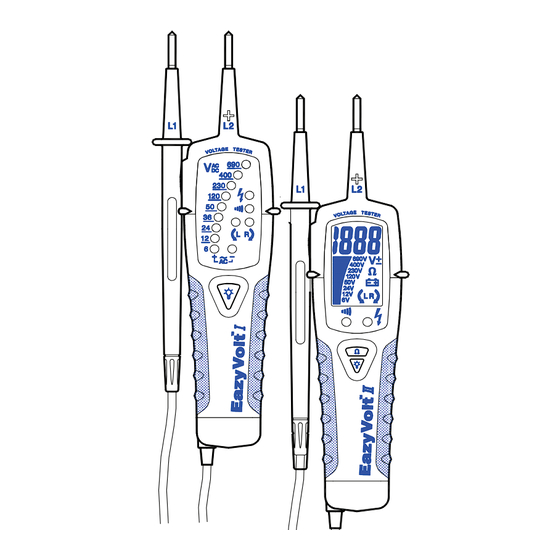
Page 4: Symbols And Features
2. Symbols and Features Symbols as marked on the Tester and Instruction manual Risk of electric shock See instruction manual + or - + DC or –DC measurement Equipment protected by double or reinforced insulation Battery Earth AC measurement Conforms to EU directives High Voltage Detection List of features AC Voltage... -
Page 5: Ac/Dc V Measurements
3. AC/DC V Measurements AC V DC V Reverse polarity with sound If the tester is used in a noisy background, you need to ensure that the soundlevel of the tester is perceptible here. -
Page 6: Continuity / Diode Test
4. Continuity / Diode Test Continuity / The Continuity / test is only possible when batteries are installed and in good condition. -
Page 7: Resistance Measurements
5. Resistance Measurements Only on EV The Resistance test is only possible when batteries are installed and in good condition. 6. Single-Pole Phase Test Single-Pole Phase Firmly... -
Page 8: Phase Rotation Test
The single-pole phase test is only possible when batteries are installed and in good condition. The single-pole phase test is not always appropriate for testing whether a circuit is not live. For this purpose, the bipolar test is required. To determine external conductors during phase tests the display function may be impaired (e.g. - Page 9 x Left rotary field Firmly Testing of phase-sequence direction is possible from 100V AC voltage (phase to phase) provided the neutral is earthed. On making contact with both test elec- trodes (probe tips) to two phases of the three-phase power supply which are connected in clock-wise rotation, a “...
-
Page 10: Rcd Voltage Test
Attention : Please ensure that the test electrodes (probe tips) make good contact with two phases of a three-phase mains while test- ing the phase rotation. For absolute deter- mination of a clock-wise phase rotation it is necessary to make a negative phase rota- tion test after changing the phases. -
Page 11: Illumination
To avoid RCD tripping, a test has to be carried out between L and N during approx. 5sec. Immediately afterwards, voltage test- ing between L and PE can be carried out without RCD tripping. 9. Illumination Probe tip torch... -
Page 12: Battery Replacement
10. Battery Replacement If no signal sound is audible (EV )when short circuiting the test probes, if the symbol “ ” is displayed (EV ) - Completely disconnect EV / EV from the measurement circuit. - Unscrew the screw by a cross screw driver, then open the battery cover. -
Page 13: Cleaning
12. Cleaning Prior to cleaning, remove the instruments from all measurement circuits. If the instruments are dirty after daily usage, it is advisable to clean them by using a damp cloth and a mild household detergent. Never use acid detergents or dissolvent for cleaning. -
Page 14: Specification
15. Specification EV I EV II Nieaf Instruments Voltage range 6….690V AC/DC LED/Bargraph 6,12,24,36,50,120, resolution 230,400, 690V 10V…690V LCD voltage range AC/DC LCD resolution Accuracy (3%rdg+2d) Voltage detection Automatic (AC Voltage) Yes Acoustic signal sound DC Voltage) Yes “ ”... - Page 15 EV I EV II Nieaf Instruments Continuity Test Threshold < 200K < 20µA Test current Overvoltage 690V AC/DC protection Rotary Field Indication Voltage range (LEDs) 100…690V Frequency range 50…60Hz Measurement Double-pole and firmly principle hold the grip (L2) Power supply 2 x 1.5V Micro IEC LR03...
-
Page 16: Warranty
16. Warranty Nieaf Instruments are subject to strict quality control. However, should the instrument function improperly during normal use, you are protected by our 6 month warranty. We will repair or replace free of charge any defects in workmanship material, provided the instrument is returned unopened and unhampered with.
Need help?
Do you have a question about the EazyVolt I and is the answer not in the manual?
Questions and answers