Table of Contents
Advertisement
Advertisement
Table of Contents
Troubleshooting

Related Manuals for Emotron VSA


Summary of Contents for Emotron VSA
- Page 1 Instruction Manual - English...
-
Page 2: Quick Start Guide
• Remove the terminal cover to expose the motor and Step5 Other settings power terminals. As for other function, please refer to VSA user manual. a. Verify that AC power is wired to L1, L2, and L3. b. Verify that motor leads are connected to T1, T2, and... - Page 3 Emotron AB 01-3993-01r1...
- Page 4 • The model and capacity of the VSD is the same as those tion provided in the manual, contact your nearest Emotron specified on your order. distributor or sales representative who will be willing to help •...
- Page 5 Emotron AB 01-3993-01r1...
-
Page 6: Table Of Contents
Contents Safety Precautions ......... 3 Model description........... 5 Mounting and installation of the VSA drive.. 7 Environment .............. 7 Mounting and installation......... 9 Wiring Rules............. 10 2.3.1 Notice for wiring ............10 2.3.2 Options and wiring specifications ......11 2.3.3 Precautions for peripheral applications .... - Page 7 Emotron AB 01-3993-01r1...
-
Page 8: Safety Precautions
(activated) to be effective, and be switched OFF (de- activated) when controlling the motor speed. The Emergency Stop command has to be switched OFF (de- activated) to become effective and needs to be ON (activated) to make normal operation possible. Emotron AB 01-3993-01r1... - Page 9 ° temperature ranging between –10 C to ° C and relative humidity of 95% or less, but the environment should be free from water and metal dust. Emotron AB 01-3993-01r1...
-
Page 10: Model Description
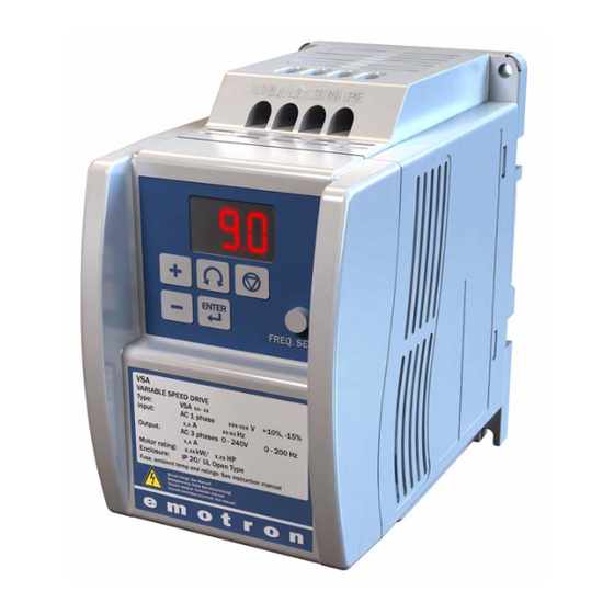
VSD model Model: VSA23-04 Input voltage I/P: AC 1 PH 200-240V 50/60Hz O/P: AC3PH 0~264V Output specifications 1.6kVA 4.2 A EMOTRON AB Input voltage Rated output current Series 23: 230V 01/03/04/07/10 A 48: 460V 002/004/005 A Emotron AB 01-3993-01r1 Model description... - Page 11 Model description Emotron AB 01-3993-01r1...
-
Page 12: Mounting And Installation Of The Vsa Drive
12 cm 5 cm 5 cm 5 cm (A) Front view (B) Side view Fig. 2 Mounting and clearance requirements • All VSA drives in IP-20 Enclosures can be DIN-RAIL Emotron AB 01-3993-01r1 Mounting and installation of the VSA drive... - Page 13 A. DIN-rail installation B. DIN-rail removal Fig. 3 DIN-rail mounting of the VSA drive • All VSA drives in IP-20 enclosures can be mounted side- by-side as shown below. (ambient temperature below 122°F) (50°C). Fig. 4 Side-by-side Mounting of the VSA Drive...
-
Page 14: Mounting And Installation
Iron filings, dust rain and water Excessively high Extremely low Strong vibration temperatures temperatures Electromagnetic waves and Radioactive materials Inflammable materials ultra high frequency waves (Near an electric welding machine) Emotron AB 01-3993-01r1 Mounting and installation of the VSA drive... -
Page 15: Wiring Rules
The following are nominal values of TM1: Type Power source Volts Amps VSA23-01/03/ 200-240V VSA23-07/10 200-240V VSA48-002/ 380-480V 004/005 NOTE: Nominal values of input and output signals (TM2) – follow the specifications of class 2 wiring. Mounting and installation of the VSA drive Emotron AB 01-3993-01r1... -
Page 16: Options And Wiring Specifications
AC drive. Additional thermal overload relays must installed in front of each motor. • Do not install phase advancing capacitors, LC, or RC components between VSD and motor. Emotron AB 01-3993-01r1 Mounting and installation of the VSA drive... -
Page 17: Precautions For Peripheral Applications
• To avoid damaging the VSD, do not connect the output terminals T1, T2, and T3 to AC input power. • Connect the ground terminal properly. (230 V series: Rg <100; 460 V series: Rg <10.): <10Ω. Fig. 5 Typical installation schematic Mounting and installation of the VSA drive Emotron AB 01-3993-01r1... - Page 18 (C) To ensure maximum safety, use correct wire size for the main power circuit and control circuit. (See table in section 2.3.2, page 11) (D) Verify that all wiring is correct, wires are intact, and ter- minal screws are secured. Emotron AB 01-3993-01r1 Mounting and installation of the VSA drive...
-
Page 19: Vsd Specification
3PH 0 to 480V Input current (A) VSD with filter Weight Lb. (kg) 3.70 (1.37) 3.75 (1.4) 3.82 (1.45) Maximum momentary power loss time (S) Enclosure IP20 * Based on a 4-Pole Motor Mounting and installation of the VSA drive Emotron AB 01-3993-01r1... -
Page 20: General Specifications
Humidity 0 – 95% RH (non condensing) Vibration immunity 1G (9.8 m/s EMI/EMS Compatibility Built-in filter in accordance with EN61800-3 first environment Accordance with EN50178 Enclosure IP20 Safety Class UL508C Emotron AB 01-3993-01r1 Mounting and installation of the VSA drive... - Page 21 VSA23-01/03/04 type (Fc=10 kHz) and VSA23-07/10 type (Fc=6 kHz) with Build in filter complies with EN61800-3 first environment unrestricted distribution. VSA48-002-005 type (Fc=10 kHz) with Build in filter complies with EN61800-3 first environment restricted distribution. Mounting and installation of the VSA drive Emotron AB 01-3993-01r1...
-
Page 22: Vsa Wiring Diagram
(Connect the 0V of the external supply to Common (terminal 8)). Example: Main circuit wiring diagram B1/P B2 R/L1 U/T1 S/L2 V/T2 T/L3 W/T3 Control circuit Cooling fan * Not used for single-phase operation Emotron AB 01-3993-01r1 Mounting and installation of the VSA drive... -
Page 23: Description Of Vsd Terminal
Control signal terminals block description 10 VDC analogue – signal Effective when parameter [212]=2 (analogue input signal from TM1) 20 mA analogue – Fig. 12 Signal terminal locations signal Mounting and installation of the VSA drive Emotron AB 01-3993-01r1... -
Page 24: Dimension
Dimension IP20 Frame 1: Single phase: VSA23-01 to 04 4- Ø*4.5 Fig. 13 VSA drive frame 1 dimensions Emotron AB 01-3993-01r1 Mounting and installation of the VSA drive... - Page 25 IP20 Frame 2: Three phase: VSA48-002 to 005 4- Ø*4.5 Fig. 14 VSA drive frame 2 dimensions LENGTH inches/ inches/ inches/ inches/ MODEL 4.86/ Frame 1 5.2/132 2.64/67 3.03/77 123.5 4.86/ Frame 2 5.2/132 4.25/108 4.65/118 123.5 LENGTH inches/ inches/...
-
Page 26: Installation And Design Consideration
NOTE 2. When connecting a drive or drives’ DC bus connections in parallel with larger Hp rated drives, use a magnetic contactor with the & terminals, otherwise, VSD damage can result. Emotron AB 01-3993-01r1 Mounting and installation of the VSA drive... - Page 27 Mounting and installation of the VSA drive Emotron AB 01-3993-01r1...
-
Page 28: Programming Instructions And Menu List
Fig. 17 Keypad Operations Sequence *2: The frequency can be set during both stop and run modes. *1: Display flashes with set frequency in stop mode, but it is solid in run mode. Emotron AB 01-3993-01r1 Programming instructions and menu list... -
Page 29: The Display
001: Reverse disable 000: Auto-run at set temperature 001: Run when VSD runs Fan control 002: Always run 003: Always stop 000: Forward/ Stop-Reverse/Stop External control operation mode 001: Run/ Stop-Forward/Reverse 002:3-wire-Run/ Stop Programming instructions and menu list Emotron AB 01-3993-01r1... - Page 30 Baud rate (bps) *3 *4 002: 9200 003: 38400 000: 1 Stop bit Stop bit *3 *4 001: 2 Stop bit 000: No parity Parity bit 001: Even parity *3 *4 002: Odd parity Emotron AB 01-3993-01r1 Programming instructions and menu list...
- Page 31 00.1 to 200 00.5/00.6 Output voltage ratio at Min fre- 00.0 to 100 01.0 quency (%) Torque boost gain (V/F) 00.0 to 30.0% 00.0 Slip Compensation Gain (V/F) 00.0 to 100% 00.0 Programming instructions and menu list Emotron AB 01-3993-01r1...
- Page 32 0 to 90 s 01.0 Min Alarm Margin 0 to 400% Min Alarm Delay 0 to 90 s 01.0 000: No AutoSet Alarm 001: Yes Normal Load 0 to 400% of max torque Emotron AB 01-3993-01r1 Programming instructions and menu list...
- Page 33 AIN Bias (%) 000 to 100 000: Positive AIN Bias 001: Negative 000: Positive AIN slope direction 001: Negative Multi-function input terminal S1 to 001 to 100 S6 signal scan time (ms ×8) Programming instructions and menu list Emotron AB 01-3993-01r1...
- Page 34 007: Momentary power loss (option) 008: Emergency Stop (E.S.) 009: Base Block (b.b.) 010: Motor overload protection 011: VSD overload protection 012: Retain 013: Power ON 014: Communication error 015: Output current detection(>[613]) Emotron AB 01-3993-01r1 Programming instructions and menu list...
-
Page 35: Menu Function Description
015 and multi-function input terminal is OFF, the fre- quency is set by the analogue signal (auxiliary speed) from TM2. If the multi-function input terminal ON, the frequency is set by the potentiometer on Keypad. Programming instructions and menu list Emotron AB 01-3993-01r1... - Page 36 000: Reverse enable (1) Input signal is NPN 001: Reverse disable S1 (run/stop) When [213]=000 and [216]=001, [336] (motor direction) is S2 (forward/reverse) disabled, the VSD is set to forward operation. COM (common) Emotron AB 01-3993-01r1 Programming instructions and menu list...
- Page 37 224 Motor rated frequency (Hz) VSD communication address: No 1 data bytes: 8 bit 225 Motor rated speed (RPM): 225 x 10= Motor rated Baud rated (bps): 38400 parity bytes: no parity speed Programming instructions and menu list Emotron AB 01-3993-01r1...
- Page 38 9KHz 13KHz 6KHz 10KHz 14KHz 7KHz 11KHz 15KHz Corresponding list of current and carrier frequency Model VSA23-01 VSA23-03 VSA23-04 VSA23-07 VSA23-10 VSA48-002 VSA48-004 VSA48-005 Carrier frequency 4 to 10K 10.5 10.5 10.0 Emotron AB 01-3993-01r1 Programming instructions and menu list...
- Page 39 241 Copy module 000: Copy module disable 001: Copy to module from VSD 263 Stop bit 002: Copy to VSD from module 000: 1 Stop bit 003: Read/write check 001: 2 Stop bit Programming instructions and menu list Emotron AB 01-3993-01r1...
- Page 40 000: Deceleration to stop ([332]: Deceleration time 1). 001: Free run to stop. 002: Deceleration to stop ([334]: Deceleration time 2). 003: Continue operating. Default=000 *Cannot be modified during communication. [266]/[267] Communication error parameter timing pat- tern. Emotron AB 01-3993-01r1 Programming instructions and menu list...
- Page 41 Master T3 > C54 Slave (VSA) Tx [551]=14 or [541]=014 0,1,2 (≠3) Frequency → dec from [332] → dec from [334] If [332]<[334] [267]=000 or 002 Frequency → free run [267]=001 Frequency Display always show “COT” → keep run until Reset “COT”...
- Page 42 We recommend that this mode stay disabled. Deceleration time = [332]× [224] (rated frequency) 3. When [335]=001 and external run mode ([213]=001), the VSD will not auto start when power is supplied and the RUN switch is ON. Emotron AB 01-3993-01r1 Programming instructions and menu list...
- Page 43 347 Skip frequency range (± Hz): 00.0 to 30.0 Example: [345]=10.0 Hz/[346]=20.0 Hz/[347]=02.0 Hz DC brake ±2 Hz=8-12 Hz Skip signal 10 Hz 20 Hz ±2 Hz=18-22 Hz frequencies [347] [346] Fig. 24 DC Injection Braking [345] Programming instructions and menu list Emotron AB 01-3993-01r1...
- Page 44 When the motor output torque is insufficient, increase too low. [352] setting value. • Decrease the value in menu [351] if the motor behaviour When the motor is vibrating excessively, decrease [352] set- gets erratic. ting value. Emotron AB 01-3993-01r1 Programming instructions and menu list...
- Page 45 [356] (Vmax) [358] (Vmid) [35A] (Vmin) [359] [357] [355] Fig. 29 User configured V/F pattern Programming instructions and menu list Emotron AB 01-3993-01r1...
- Page 46 Gain= compensation gain • Torque/Speed curve pattern: Fig. 31 Slip Compensation • Operating frequency range: 0 to motor rated frequency. • When the motor output rotation speed is too low increase [354] setting value. Emotron AB 01-3993-01r1 Programming instructions and menu list...
- Page 47 000: PID Function disabled. 001: PID Control, Deviation is derivative controlled. 002: PID Control, Feedback is derivative controlled. 003: Same as 001 but (reverse characteristics control). 004: Same as 002 but (reverse characteristics control). Programming instructions and menu list Emotron AB 01-3993-01r1...
- Page 48 002: Max, Max Alarm active. The alarm output functions as an overload alarm. 003: Max+Min, Both Max and Min alarm are active. The alarm outputs function as overload and underload alarms. Speed Emotron AB 01-3993-01r1 Programming instructions and menu list...
- Page 49 41D Min Alarm Delay: 0-90 s Sets the delay time between the first occurrence of min alarm condition and after when the alarm is given. 41E Autoset Alarm: 000: No 001: Yes Programming instructions and menu list Emotron AB 01-3993-01r1...
- Page 50 When run signal is applied and the selected external age. multi-function input terminal is on and set to Jog speed, the VSD will run according to [348] setting. Emotron AB 01-3993-01r1 Programming instructions and menu list...
- Page 51 Set [212]=003, to enable the Up/Down function. Note: the Up/Down key on the keypad is unavailable for changing frequency directly. Set [361]=000, When Up/Down terminal is ON, the VSD begins acceleration/deceleration to a frequency and Programming instructions and menu list Emotron AB 01-3993-01r1...
- Page 52 [338]; When TM2 DC Brake signal is ON, and the brake time in menu [338] has already been over, the brake is stopped according to DC Brake signal OFF of TM2. Emotron AB 01-3993-01r1 Programming instructions and menu list...
- Page 53 Extend [513] if noise is a prob- lem, however the response speed will be slower. 518: Multi-function input terminal S1 to S6 signal scan time (N. ms ×8), N=(1 to 100 times). Programming instructions and menu list Emotron AB 01-3993-01r1...
- Page 54 Up/Down key on the keypad is unavailable for changing frequency directly. Set [361]=000, When Up/Down terminal is ON, the VSD begins acceleration/deceleration to a frequency and stops acceleration/ deceleration when the Up/ Down sig- Emotron AB 01-3993-01r1 Programming instructions and menu list...
- Page 55 When the external control terminal ON, the VSD will over, the brake is stopped according to DC Brake signal stop acceleration/ deceleration will the signal is released. OFF of TM2. The motion is as follows: Programming instructions and menu list Emotron AB 01-3993-01r1...
- Page 56 S1-S4 & AIN and also setting of parameters [521] to [524] as required. NOTE 2: Selected preset frequency values should be programmed in parameters [362] to [369] as required. Emotron AB 01-3993-01r1 Programming instructions and menu list...
- Page 57 No operation signal or command frequency do not coincident, relay inactive Fig. 36 Frequency Reached [551]/[541]=2 [551]/[541]=003 Frequency detection fout>[611] Operation command [213] Setting frequency [611] INV output frequency Setting frequency [611] Relay output signal Fig. 37 Frequency Detection [551]/[541]=3) Programming instructions and menu list Emotron AB 01-3993-01r1...
- Page 58 [614]: Setting value (00.0 to 25.5) unit: secconds 811 Fault records (Latest 3 times) Refer to section 4.1, page 55 for description of fault types. 922 Software version 921 VSD horse power capacity Emotron AB 01-3993-01r1 Programming instructions and menu list...
- Page 59 Programming instructions and menu list Emotron AB 01-3993-01r1...
-
Page 60: Troubleshooting And Maintenance
High heat sink tem- 1. Heavy load 2. Increase VSD capacity perature during oper- 2. Ambient temperature too high or bad ventila- 3. Improve ventilation conditions ation tion 4. Inspect the setting value of parameter [217] Emotron AB 01-3993-01r1 Troubleshooting and maintenance... -
Page 61: Set Up Configuration, Interface Errors
2. When REMOTE KEYPAD connects with VSD, this signal will be displayed on the main - - - broken keypad. 3. When both REMOTE KEYPAD and main KEYPAD display this signal means communica- tion errors. Troubleshooting and maintenance Emotron AB 01-3993-01r1... -
Page 62: Keypad Operation Error Description
2. Check the monitor setting in [411] to [429]. 1. Check the load condition of the machine. Pre-alarm overload Actual load reaches maximum pre-alarm margin. 2. Check the monitor setting in [411] to [429]. Emotron AB 01-3993-01r1 Troubleshooting and maintenance... -
Page 63: General Functional Troubleshooting
Increase capacities of the VSD and the motor. incorrect or erratic Add an AC reactor at the power input side if using Is the load too large? single-phase power. Check wiring if using three-phase power. Troubleshooting and maintenance Emotron AB 01-3993-01r1... -
Page 64: Troubleshooting Flowcharts Vsa Series
4.2.1 Troubleshooting flowcharts VSA series VSA faults Is fault fully understood? Symptoms other than burn Any signs of burnout Check and replace burnt and out, damage, or fuse melt-down and damage? damaged parts in the VSD? Is the main circuit... - Page 65 * from previous page Check the menus in the VSA Perform menu initialization Specify operation control method Set up frequency commands Is the frequency value displayed in the operating unit? Replace the control board Are there voltage outputs in Replace the control...
- Page 66 Troubleshooting for OC, OL error displays The VSA displays OC, OL errors Is the main circuit Replace I.G.B.T I.G.B.T working? Any abnormalities Replace faulty circuit board in appearances? Apply the power Is the current Any faults? detector OK? Replace the current sensing...
- Page 67 Troubleshooting for OV, LV error display The VSA displays OV, LV errors Is the main circuit Replace the main circuit board fuse intact? Apply the power Replace the control board Fault message Input operation commands Input frequency commands Is the output frequency of the...
- Page 68 Is the voltage between L1-L2, Bad power quality L2-L3, L3-L1 leads correct? or wiring incorrect LED indicator lit? VSA fault Is the operation switch Set switch in “RUN” position in RUN position? Is there T1, T2 and T3 output? VSA fault...
- Page 69 Does it happen time correct for the Increase the acc/dec time in acc/dec? application? Reduce the load. Increase or ratings for the VSA and the motor. Are output voltage between T1-T2, T2-T3, VSA faults T3-T1 balanced? YES (within ±3% of rated output voltage)
-
Page 70: Routine And Periodic Checks
Replace power compo- nent Ο ken circuit in three- each terminals multi-tester nent or VSD phase output Ο Any unusual odour or leakage Replace capacitor or Capacitor Visual check No abnormalities Ο Any deformity or protrusion Emotron AB 01-3993-01r1 Troubleshooting and maintenance... - Page 71 Troubleshooting and maintenance Emotron AB 01-3993-01r1...
-
Page 72: Peripherals
Input side AC reactor JNSIF-485 wiring diagram: Single/three-phase power supply Line input side AC inductance RS485 Model Current inductance (mH) JNSIF-485 VSA series 23-01 24 V 23-03 Black 23-04 19.0 23-07 25.0 0.71 Fig. 49 JNSIF-485 wiring diagram 48-002 48-004... -
Page 73: Program Copy Option Card (Copy Unit) (Jnsif-Mp)
5.2.4 Remote keypad (Remote JNSIF-232 wiring diagram keypad) (Model: JNSDOP-LED- VSA series RS-232 CON302 (12P) JNSIF-232 Red cable to 24 V 1.8 m Black cable to COM Fig. 51 JNSIF-232 wiring diagram 5.2.3 Program copy option card (Copy Unit) (JNSIF-MP) Fig. -
Page 74: Input/Output Expansion Card (Model: Jnsif-Io)
(model: JNSIF-IO) Red cable to 24 V Black cable to COM Fig. 55 JNSIF-IO card JNSIF-IO wiring diagram Single/three- phase power supply 24 V VSA series 2 in 1 CON302(12P) Out card Fig. 56 JNSIF-IO Wiring Diagram Emotron AB 01-3993-01r1 Peripherals... - Page 75 Peripherals Emotron AB 01-3993-01r1...
-
Page 76: Appendix Vsa Parameter List
Appendix VSA parameter list Customer Name Model of the VSD: Menu Setting Menu Setting Menu Setting Emotron AB 01-3993-01r1 Appendix VSA parameter list... - Page 77 Appendix VSA parameter list Emotron AB 01-3993-01r1...
- Page 79 Emotron AB, Mörsaregatan 12, SE-250 24 Helsingborg, Sweden Tel: +46 42 16 99 00, Fax: +46 42 16 99 49 E-mail: info@emotron.se Internet: www.emotron.com...
Need help?
Do you have a question about the VSA and is the answer not in the manual?
Questions and answers