Table of Contents
Advertisement
Quick Links
Advertisement
Table of Contents

Related Manuals for GDS SP40 PLUS series


Summary of Contents for GDS SP40 PLUS series
- Page 1 User Manual for family MAN10239-02...
-
Page 3: Eec Regulations
User Manual Family Compuprint Product Information Thanks for choosing the Compuprint SP40plus printer. Your printer is a reliable working equipment that will be very useful in your daily job. Our printers have been designed to be compact and respectful of the work environment. They offer a wide range of features and multiple functions that confirm the high technological level reached by Compuprint printers. -
Page 4: Table Of Contents
User Manual Family Table of Contents Compuprint Product Information Serial Interface Canadian D.O.C. USB Interface Radio Interference Regulation LAN Interface EEC Regulations Table of Contents Printer Setup (with configuration pages) Printer Family Presentation Entering the Printer Setup Mode Technical Specifications (common to all Printing the Self Test Page models) Printing the Printer Setup Forms... -
Page 5: Table Of Contents
User Manual Family Table of Contents cont’d Printing Problems Passbooks with Vertical Fold Scan Problems Paper specifications for Fanfold Hexadecimal Dump Serial Interface Paper Specification Magnetic Media Cut Sheets Magnetic Ink Character Recognition Passbooks Magnetic Strip Read/Writer Passbooks with Horizontal Fold User Information according the European Directive 2002/95/EC and 20003/108/EC MAN10239-02... -
Page 6: Printer Family Presentation
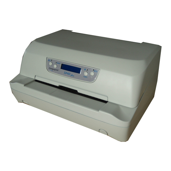
User Manual Family Printer Family Presentation The SP40Plus is a family of multi-purpose dot-matrix printers for front office applications. Its compact structure is designed for integration in an ergonomic environment. The printer provides a high level of reliability, form-handling accuracy and data integrity. This is the complete list of the SP40Plus family. -
Page 7: Technical Specifications (Common To All Models)
User Manual Family Technical Specifications (common to all models) 24 pin serial dot matrix printer (needle diameter 0,25 mm) Printing Technology 520 cps Printing Speed Draft 400 cps (@10 cpi) 200 cps 133 cps 94 columns @10 cpi – 112 columns @ 12 cpi – 141 columns @ 15 cpi Line Length Single Sheet, envelopes, labels, ID cards (paper weight from 40gr/m to 200... -
Page 8: Technical Specifications (Model Dependent)
User Manual Family Technical Specifications (model dependent ) Fanfold (continuous form) Paper Handling Standard model up to 240 mm (9.45 inch) Wide model up to 250 mm (9.84 inch) Front / Rear colour scanner, 16 million colours RGB, 256 grey scale levels, up to Scanner 600 DPI, Twain compatible Magnetic Strip Read/Write, 4bit code, reading speed up to 13 inch/sec., decoded... -
Page 9: Unpacking The Printer
User Manual Family Unpacking the Printer Together with the printer the following items are included in the shipment box: Notify any damage to your supplier. Ribbon Cartridge Power Cable CD-ROM with printer documentation and drivers. Quick Reference Guide Only for tractor model Ribbon Cartridge Power Cable Tractor Unit... -
Page 10: Printer Parts
User Manual Family Printer Parts Never remove any printer part unless it is expressly indicated in this manual. Front Views MAN10239-02... -
Page 11: Front Views For Tractor Model
User Manual Family Front Views for tractor unit MAN10239-02... -
Page 12: Rear Views
User Manual Family Rear views In the rear part of the printer are the AC power connector and all the interface connectors. Depending by the models, the available interfaces can be different. Optional interfaces available (parallel, 2x Serial, USB, 2x USB-Hub, LAN) Rear view for tractor unit For the tractor model only in the rear part of the printer together with the AC power connector and all the interface connectors, there is tractor unit connector and gear, visible on the left side.. -
Page 13: Inside Views
User Manual Family Inside view Inside Views MAN10239-02... -
Page 14: Printer Installation
User Manual Family Printer Installation Choosing a Suitable Location Consider the following points when you choose the location for your printer: The distance between the printer and the host computer must not exceed the length of the interface cable; The location must be sturdy, horizontal and stable; Your printer must not be exposed to direct sunlight, extreme heat, cold, dust or humidity;... -
Page 15: Installing The Ribbon Cartridge
User Manual Family Installing the Ribbon Cartridge In order to avoid damaging the print head or mechanical gearings, this printer accepts only original Compuprint ribbon cartridges. Therefore, if you install a not original cartridge, the printer may not work. Remove the cartridge from its bag. Unhook the green ribbon mask from the cartridge pins. - Page 16 User Manual Family Open the upper mechanical frame. Locate the open green lever in the left side of the printer. Unhook the green lever with the left hand towards the rear of the printer in the open position. Then rise up the lever to its maximum position in order to completely open the head assembly.
- Page 17 User Manual Family The printer is now ready to install the ribbon cartridge. Turn the tension knob in the direction of the arrow to tighten the ribbon. Insert the upper cartridge pins onto the corresponding grooves on both sides of the upper mechanical frame.
- Page 18 User Manual Family Insert the green plastic ribbon mask onto the print head. Pay attention to match the two pins (2) on both sides of the green ribbon mask with the grooves (1) on both sides of the print head. Push the green ribbon mask up until it clicks into place.
-
Page 19: Installing The Tractor Unit
User Manual Family Installing the Tractor Unit In order to avoid damages, always install or remove the tractor unit in power-off status. Do not swap the tractor unit in other printer unit because it requires a paper sensor calibration procedure through technical diagnostic. 1. - Page 20 User Manual Family 4. Then, press the tractor unit lock lever while put the tractor unit in position until they sound a click. 5. Open the right tractor lever and move the right tractor as the paper width. Open the tractors cover and install the paper on it.
-
Page 21: Connection To The Host
User Manual Family Connection to the Host This printer can be connected to the host by means of the following available interface ports: 1. Parallel standard Centronics or bi-directional IEEE 1284 type interface 2. Serial RS-232/C interface 3. USB 2.0 full speed interface 4. -
Page 22: Installing The Power Cable
User Manual Family Installing the Power Cable Find the power cable connector and the rating plate on the rear side of the printer. Always use a grounded outlet Insert the power cable into the connector on the printer and the other end into a convenient mains outlet. -
Page 23: Paper Handling
User Manual Family Paper Handling This printer is designed for versatile and reliable paper handling. The flat-bed mechanism allows the handling of special documents, such as multiple invoices, postcards, labels, passbooks and tickets. The print head detects the paper edges automatically, the sheet can therefore be inserted in any position within the detection area according to the rules described in the following paragraph. - Page 24 User Manual Family The different type of loaded media must be loaded with respect the area merkers highlighted on the front cover flap. The document may not exceed the limits of the paper stand. Correct fanfold loading position MAN10239-02...
- Page 25 User Manual Family Correct cheque loading position (CMC7 codeline side on the bottom) Correct passbook loading position (magnetic codeline side on the bottom) MAN10239-02...
-
Page 26: The Operator Panel
User Manual Family The Operator Panel The operator panel is located in the middle of the printer cover and is composed of four function keys and four leds with which you can easily check the printer status and select the functions. Some models are equipped with a wide LCD 2x16 characters display for an easiest and visible status and/or error condition. -
Page 27: Function Keys
User Manual Family Function Keys NORMAL MODE SETUP MODE SPECIAL MODE When using the IBM 4722, IBM 9068 and When the Printer is in When pressed while the Olivetti protocols in two operators Printer Setup powering the printer on with (“booking”) mode, the application software mode, pressing this READY key selects the T&D... -
Page 28: Leds
User Manual Family Leds NORMAL MODE SETUP MODE SPECIAL MODE Lit if paper presence, Unlit without paper If the printer is in Setup Blinks, together with the (no Olivetti). Mode, this led indicates ST2 led, if a printer error When using the IBM 4722, IBM 9068 and which setup page... -
Page 29: Lcd Display Messages
User Manual Family LCD display messages (only for the model with it) Upper line message Indication Lower line message The printer initialization phase is starting-up. STARTING UP The printer initialization phase is ended ..INIT.. The printer firmware release message SP40plus Rel. xxx The printer is in normal ready status showing the current Program and the current Font. -
Page 30: Software Driver Selection
User Manual Family Software Driver Installation With the printer is shipped a CD with drivers and manuals in PDF format and the drivers for the most used Operating Systems and other tool for printer installation. For the SP40Plus family, these drivers are available on the latest CD 78411708-014: Windows 10 –... - Page 31 User Manual Family Install prompt masks Wait installation end. Starting from O.S. Windows 7 and later the driver, when the interface cable will be connected, the O.S. will detect the printer supporting Plug&Play utility and the Driver will be automatically installed. For O.S.
-
Page 32: Twain Driver
User Manual Family If more than one driver is already present in the host, choose the latest one. Twain Driver To be used in application requiring twain driver, a specific installation Setup has been issue. It is called Twain Install.exe. It is located in the folder: ..\source\Drivers\ Compuprint SP40_SP40Plus_SP40PlusT\TWAIN DRIVER Double click on it. -
Page 33: Unix Driver
User Manual Family Unix Driver The file cmpwizard.sh is located in the folder : ..\source\Drivers\Unix Linux Driver The file Compucupsdrv_linux_v1.0.zip is located in the folder : ..\source\Driver Linux\ CompuprintSP40Plus Extract the Compucupsdrv_linux_v1.0.tar installation file. A specific Debian GNU/Linux, ubuntu installation procedures is present in the same folder. CDC Driver To be used in SP40Plus Setup application requiring a driver converting the serial port in a USB port. -
Page 34: Setting The Interface Parameters
User Manual Family Setting the Interface Parameters Parallel Interface The parameters set for the parallel interface mainly match of the most common environments and the printer can be used immediately after connection to the host. In case you need to modify the standard parameters see Printer Setup or Remote Printer Setup later in this section. -
Page 35: Entering The Printer Setup Mode
User Manual Family Printer Setup (with configuration pages) The Printer Setup is used to configure the printer parameters and to print a Self Test page, to check the settings and the printer installation, and to perform the Print Offset Tuning. The default configuration of this printer matches most of the commonly used environments, but it may be necessary to change some printer parameters. - Page 36 User Manual Family Self Test SP40Plus basic model MAN10239-02...
- Page 37 User Manual Family Self Test SP40Plus LAN model MAN10239-02...
- Page 38 User Manual Family Self Test SP40Plus MULTIFUNCTION model MAN10239-02...
- Page 39 User Manual Family Self Test SP40Plus TRACTOR model MAN10239-02...
-
Page 40: Printing The Printer Setup Forms
User Manual Family Printing the Printer Setup Forms If you already have the pre-printed Setup forms, go to “Filling in the Printer Setup Forms” later in this manual. 1. With the printer in Setup Mode, insert a blank sheet in A4 or Letter format. 2. - Page 41 User Manual Family Configuration Setup SP40Plus basic model MAN10239-02...
- Page 42 User Manual Family Configuration Setup SP40Plus LAN model MAN10239-02...
- Page 43 User Manual Family Configuration Setup SP40Plus MULTIFUNCTION model MAN10239-02...
- Page 44 User Manual Family Configuration Setup SP40Plus TRACTOR model MAN10239-02...
- Page 45 User Manual Family Program Setup SP40Plus basic model MAN10239-02...
- Page 46 User Manual Family Program Setup SP40Plus LAN model MAN10239-02...
- Page 47 User Manual Family Program Setup SP40Plus MULTIFUNCTION model MAN10239-02...
- Page 48 User Manual Family Program Setup SP40Plus TRACTOR model MAN10239-02...
-
Page 49: Filling In The Printer Setup Forms
User Manual Family Filling in the Printer Setup Forms To change the values of the parameters, fill in the marker ( ) beside the value you want to set with a black or blue ball-point pen or a fiber-pen. Do not use pencil. AUTOFEED SIGNAL ( ) disabled * enabled... - Page 50 User Manual Family Setup Parameter Values Description ERROR BUZZER Disable, enable* Enables or disables the buzzer in case of an error. JOB BUZZER no beep*, Selects the behavior of the buzzer when a new 1 beep, continuous print job starts: no signal (no beep), one beep (1 beep) or a continuous signal (continuous).
- Page 51 User Manual Family Setup Parameter Values Description GET EDGE QUOTE 0/4”, 1/4”*, 2/4”, 3/4”, Sets the position in which the left paper edge is 4/4”, 5/4”, 6/4”, 7/4 checked. If set to 0, the check is performed at the first line. The other values correspond to the physical distance from the first line.
- Page 52 User Manual Family Setup Parameter Values Description SPACE DETECT Disabled, enabled* Selects space detection of MICR EJECT Command*, Auto Select the mode of eject magnetic media RETRY Select the number of retry of the MICR band read. Example: How to set the Retry to 2: ( )0 ( )1 █...
-
Page 53: Program Setup
User Manual Family Program Setup Setup Parameter Values Description PROTOCOL EPSON 570*, IBM X24E* Defines the printer protocol. X24E AGM, IBM 2390, NOTE: For the IBM 4722 and 9068 protocols, if OLI. PR40+, OLI. PR2*, the software driver uses the controlled link of OLI. - Page 54 User Manual Family Setup Parameter Values Description LEFT MARGIN 10 x Sets the left margin in number of columns. The values range Minimum=0 between 0 and 90. To set the values combine the numbers Maximum=90 considering that the first line corresponds to the tens, the Current=0 second line to the units.
- Page 55 User Manual Family Setup Parameter Values Description IBM C-SET IBM set 1*, IBM set 2 Selects the IBM character set. IBM COMPRESS 17.1 cpi*, 20 cpi Selects the pitch for the compressed mode printing in IBM emulation. EPSON C-SET Italic, graphic* Selects italic or graphic Epson character set.
- Page 56 User Manual Family Setup Parameter Values Description WRAP MODE truncate, autowrap* The data exceeding the line length are truncated (truncate) or printed on the following line (autowrap). SLASHED ZERO No*, yes Selects the printing character for zero, with a slash (yes) or without (no). EJECT ON FF no, yes* Performs a form feed according to the...
-
Page 57: Offset Adjustment
User Manual Family Offset Adjustments For a precise adjustment of the position of the printed characters on a pre-printed form, the printer allows to easily adjust the first line and the first printing column as follows: When the printer is in Setup Mode, load a blank sheet into the printer press the ST1 key until the leds are in the configuration showed in previous SETUP STATUS table. -
Page 58: Reading The Pre-Printed Setup Forms
User Manual Family The Vertical Offset Tuning values correspond to 1/60 inches and set the vertical offset of the first print line starting from the default standard position at 1 mm from the upper paper margin. The Horizontal Offset Tuning values correspond to 1/60 inches and set the horizontal offset of the first print line starting from the default standard position at 3 mm from the left paper margin. -
Page 59: Printer Setup Flow Chart
User Manual Family Printer Setup Flow Chart Printer Ready Setup Mode Printer OFF # Parameters are set Self Test ● MAN10239-02... -
Page 60: Printer Remote Setup
User Manual Family Printer Remote Setup The printer Setup parameters can be changed through normal Setup as described in previous chapter or through USB (using a virtual COM port) or through Serial 232/C port. For this purpose is necessary install the ”Compuprint CDC RS-232 Emulation” driver creating a virtual serial port and the “SP40plus Remote Setup Tool”... -
Page 61: Sp40Plus Remote Setup Installation
User Manual Family If the installation is positively ended, in the Windows hardware resources a new COMn port will be found. SP40Plus Remote Setup Tool installation Once the Compuprint CDC RS-232 Emulation driver has been installed, found the Setup.exe file and double click on it. - Page 62 User Manual Family If the installation is positively ended, in the programs Window, the SP40Plus Remote Setup Tool icon will appear. Double click on it and the SP40Setup utility will be run. The SP40Plus Remote Setup Tool is now at 2.0.25 release. When this utility is running, the following home mask will be displayed.
- Page 63 User Manual Family In the Select Active Port selection the available ports are listed. The first available port number used by the Setup utility is taken from the system registry and can be different from the one displayed. If another Serial-USB adapter is connected to the printer, it will be possible to see another COM port.
- Page 64 User Manual Family When the Read NVM key is pressed, a pop-up message appear to advise to a specific action. After a short time (time to recover data from NVM), the tool will show: 1) The printer FW details: Model Release 2) All the parameters of the printer as printed in the Self Test...
- Page 65 User Manual Family PROGRAM 1 SETUP Note: the other PROGRAM 2, 3 and 4 will be visible by simply scroll with the right vertical bar. After the changing of the proper Setup values, press the Write NVM to store the new values in NVM. In the same time the tool will browse a folder in which store the default configuration name as: wnvm.dmp...
-
Page 66: Lan Setup
User Manual Family LAN Setup The LAN parameters can be changed in different modes: 1) Using the SP40Plus Remote Setup Tool as detailed in previous chapter 2) Using the LANPAR parameters (only through parallel interface) 3) Using the NetViewMaster Tool (this tool can be used starting from the printer FW release 1.87 and require the lan parameters to be already set ). -
Page 67: Using The Lanpar Parameters (Only Through Parallel Interface)
User Manual Family Using the LANPAR parameters (only through parallel interface) The LAN interface parameters can be changed using two text files below detailed and sent them through parallel interface. Prompt: copy lanpar.hdr %2 /b copy %1.txt %2 /b The lanpar.hdr plus lanper.txt commands set the LAN parameters for this device. DC4 DC4 ESC DC4 <n1>... - Page 68 User Manual Family arguments example: HOST NAME=DEFAULT LOCATION=No location CONTACT=No contact IP ASSIGN=fixed IP ADDRESS=127.000.000.000 NET MASK=255.255.255.000 DEF.GATEWAY=000.000.000.000 WORKGROUP=P_NFFPS_TO SMTP=disabled MAIL SERV.ADD.=000.000.000.000 SENDER ADDRESS=No address DESTIN.ADDRESS=No address Command example: MAN10239-02...
-
Page 69: Using The Netviewmaster Tool
User Manual Family Using the NetViewMaster Tool The NetViewMaster Utility is a software tool for network administrators that allows the configuration and control of Compuprint Serial Matrix Printers remotely connected to the Ethernet LAN. With this tool the installed printers may be controlled, configured and organized easily. The main features are: 1) Device Discovery: searches for the devices within a range of IP addresses. - Page 70 User Manual Family If the installation is positively ended, in the programs Window, the NetViewMaster Utility icon will appear. In the same icon it is possible to find a detailed Guide for its usage, please refer to it for detailed information. In this chapter will be described only the basic functions.
- Page 71 User Manual Family 3) Status Menu This menu allows you to : Check Now Selecting this function the NetViewMaster Utility performs a check on all printers connected to the network and updates all the printer status. Check List Printers W/E Selecting this function the NetViewMaster Utility performs a check on all printers connected to the network and will show only the printers that are “On-line”...
- Page 72 User Manual Family The Tool Bar contains the icons of the shortcuts for the most commonly used menu functions. The Printer Database window shows an organized list of printers, configuration files, and firmware download files. The Netviewmaster’s main features are the collection, organization, and management of the printer database.
-
Page 73: Automatic Device Discovery
User Manual Family Automatic Device discovery This procedure is useful for setting up the printer database for the first time. The NetViewMaster Utility searches for the connected printers within a specified IP-address range by sending a burst of directed SNMP requests to each IP address within the range. During the device discovery procedure the NetViewMaster Utility maps Compuprint Serial Matrix Printers for complete management, getting the proprietary MIB objects supported. - Page 74 User Manual Family 1) Selecting the founded printer the complete Tool Bar Icons are highlighted 1) Selecting the Remote Panel Management icon 1) Selecting Printer Configuration icon and the printer configuration loading. 2) Select the value of item. In the Configuration menu is possible to: Send Modified Value Send All Values...
-
Page 75: Using A Browser To Access Built-In Printer's Webpages
User Manual Family Using a browser to access built-in printer’s webpages If the IP address of the printer is already set and know, it is possible to see its built-in web pages simply by digit the IP address on the browser. This is the Home page. - Page 76 User Manual Family Printer Configuration page The following Menu are available: 8) Configuration 9) Program 1 (showed) 10) Program 2 11) Program 3 12) Program 4 13) LAN Setup 14) System Printer Configuration page The following Menu are available: 15) Configuration 16) Program 1 17) Program 2 18) Program 3...
- Page 77 User Manual Family Reboot Page Message to advise the printer reset. Printer Status Page System Menu Page It is possible to restore to default MFG values all the parameters. Set the Serial Number for USB Set a new password in security MAN10239-02...
-
Page 78: Scanner & Msrw Demo Tool
User Manual Family Scanner & MSRW Demo Tool The CD shipped with the printer contains a demo to exercise the SP40plus in the MSRW and Scanner functions. The installation Setup.exe file is stored in the folder: ..\source\SP40_SP40Plus_MFP_DOC_and_Example\Demo\SP40wrap\Demo Installation Double click on it. After the installation, look at the Programs and run the SP40_mlt_if SP40 Mlt If Setup home page Home page of the Demo Tool... - Page 79 User Manual Family Setup Scanner parameters: Set image directory Set fast or normal eject Set image crop windowing Set Front and rear image parameters Set data for MSRW Message when Write Passbook is run Mask for Read Passbook data Done Mask for Read Serial Done (a serial interface must be physically connected).
- Page 80 User Manual Family TESTS INDEX Print Document mask prompt to folder to select a printable file. Mask for Read Cheque The CMC7 codeline read is written on the left. This is the result after the Scan Document selection. MAN10239-02...
- Page 81 User Manual Family This is the result after the Multi Scan Document selection. After the scan action, the Save with name for the multipage file in PDF format is done in the folder you select. MAN10239-02...
-
Page 82: Troubleshooting
User Manual Family Troubleshooting Error Handling There are two types of error: Recoverable errors Not-recoverable errors Recoverable errors When an error of this kind occurs: 1. The printer is disabled with the ST1 and ST2 led flashing and the printer sounds a beeps. 2. -
Page 83: Not-Recoverable Errors
User Manual Family Not-Recoverable errors When an error of this kind occurs: 1. The printer is halted with all the four leds flashing. 2. With operator panel with display, the following messages will be displayed; the first line indicates the error, while the second line gives more details concerning the error conditions. -
Page 84: Paper Problems
User Manual Family Paper Problems The straight paper path of this printer is designed for trouble-free handling of a great variety of documents. Paper Damaged after Printing If the paper is damaged after printing, it probably does not correspond to the specifications given in this manual or was not loaded according to the indications given. -
Page 85: Printing Problems
User Manual Family Printing Problems If the printout is fade in a side (left or right), the problem could depend by the not- correct closure of the upper mechanical assembly. Check for the correct green lever in closed and locked position. If the printout is light, disaligned and a rhombus character is printed, the problem could depend by a carriage block done by a... - Page 86 User Manual Family If the printer dipslay a ribbon error, the error could depend by the incorrect installation of the ribbon toward the rear contact located in the rear side of the ribbon. If the printout is smudged, check if the ribbon green support is correctly installed.
-
Page 87: Scan Problems
User Manual Family Scan Problems If the image from the scan action has some black areas (vertical lines or spot), the problem could be the external surface of the scanner dirty (residual of ink, glue, etc.). Open the upper mechanical assembly and clean the scan plastic surfaces with a soft damp cloth. -
Page 88: Paper Specification
User Manual Family Paper Specifications The documents must all guarantee the following characteristics: Use paper matching the indicated characteristics. They must have well defined top and left edges, with a square angle tolerance of 0.1° on all edges. Paper with holes, perforations, folds or tears anywhere within the print area of the document cannot be feeded from the front input chute, but could be eventually managed by the rear tractor requesting the specific Compuprint SP40plus model. -
Page 89: Passbooks
User Manual Family Passbooks Minimum Maximum Paper Weight 75 g/m 120 g/m Thickness (overall, within cover spine) 2.7 mm (0.106 in.) Multiple Page Passbooks (except cover spine) Horizontal/vertical Fold 0.28 mm (0.011 in.) 1.80 mm (0.071 in.) Thickness difference across the fold of an open passbook Horizontal/Vertical Fold 1.52 mm (0.059 in.) Single Page Passbook or Ledger Cards... -
Page 90: Passbooks With Horizontal Fold
User Manual Family Passbooks with Horizontal Fold Insertion direction Print Area ABCD ABCD Print Area Dimension Maximum Minimum Passbook width 241 mm (9.488 in.) 110 mm (4.33 in.) Passbook length 220 mm (8.66 in.) 130 mm (5.12 in.) Distance between print character 3.0 mm (0.118 in.) position and left or right edge Distance between top edge of the... -
Page 91: Passbooks With Vertical Fold
User Manual Family Passbooks with Vertical Fold Insertion direction ABCD Print Area ABCD ABCD Dimension Maximum Minimum Passbook width 241 mm (9.488 in.) 110 mm (4.33 in.) Passbook length 220 mm (8.66 in.) 85 mm (3.34 in.) Distance for the dot position nearest to 3,0 mm (0.118 in.) the left or right edge Distance from the top edge of the... -
Page 92: Paper Specifications For Fanfold
User Manual Family Paper Specifications for Fanfold The documents must all guarantee the following specification: Quote Printer Model PRT0626-TT PRT0621-TT Form width 79 mm 240 mm 79 mm 250 mm (3.11 inch) (9.45inch) (3.11 inch) (9.84inch) Length of module (*) 68.6 mm 304,8 mm 68.6 mm... - Page 93 User Manual Family MAN10239-02...
-
Page 94: Serial Interface
User Manual Family Serial Interface Connection Solder side Solder side view view To PC IBM To printer compatible Female connector Female connector MAN10239-02... -
Page 95: Magnetic Media
User Manual Family Magnetic Media Magnetic Ink Character Recognition The Compuprint SP40Plus printer with horizontal MICR option is used to read and decode bank cheque code-line. Here below are reported the device technical specifications. Standard supported: CMC7 and E13B Reading Speed: 0.7 m/sec (27 ips) Character recognition throughput: CMC7 0.9 sec. - Page 96 User Manual Family ANSI standard Bit density 210 Bit Per Inch ± 5% Preamble 20 “zero” bits Postamble 20 “zero” bits Start sentinel (SOM) End sentinel (EOM) Recordable characters 0-9 and “E” Recording direction Left to Right Center of vertical position 13,9 mm Horizontal start position 9.5 mm.
- Page 97 User Manual Family - DIN/ISO/ANSI Standard Lay-out IBM 6304 Standard Lay-out BORROUGHS Standard Lay-out MAN10239-02...
-
Page 98: User Information According The European Directive 2002/95/Ec And 20003/108/Ec
User Manual Family User Information according to European Directive 2002/95/EC and 2003/108/EC This unit must be recycled or discarded according to applicable local and national regulations. The symbol shown above, applied to the product or on its packing, indicates that, at end of life, the product is not to be thrown away, or disposed as unsorted municipal waste, but separately collected. - Page 100 COMPUPRINT s.r.l. Via Lombardore, 282 10040 Leinì (TO) ITALY SPECIFICATIONS ARE SUBJECT TO CHANGE WITHOUT NOTICE. This manual refers to various company and products by their trade names. In most of the cases, these designations are claimed as trademarks or registered tramarkers by their respective companies.
Need help?
Do you have a question about the SP40 PLUS series and is the answer not in the manual?
Questions and answers