Table of Contents
Advertisement
Advertisement
Table of Contents

Related Manuals for FLYGT 2125


Summary of Contents for FLYGT 2125
- Page 1 Installation, Operation, and Maintenance Manual 2125...
-
Page 3: Table Of Contents
Install the pump..........................16 Sedimentation prevention......................16 Discharge line requirements......................16 Fasteners............................17 Install with S-installation.........................17 Make the electrical connections......................18 General precautions........................18 Requirements..........................18 Cables..............................18 Earthing (Grounding)........................19 Earth (ground) conductor length....................19 Connect the motor cable to the pump..................19 Cable charts............................20 2125 Installation, Operation, and Maintenance Manual... - Page 4 The pump starts-stops-starts in rapid sequence................39 The pump runs but the motor protection trips................40 The pump delivers too little or no water..................40 Technical Reference..........................42 Application limits..........................42 Motor data............................42 Specific motor data...........................42 Dimensions and weights........................46 Performance curves..........................50 2125 Installation, Operation, and Maintenance Manual...
-
Page 5: Introduction And Safety
A hazardous situation which, if not avoided, could result WARNING: in death or serious injury A hazardous situation which, if not avoided, could result CAUTION: in minor or moderate injury 2125 Installation, Operation, and Maintenance Manual... -
Page 6: Inspect The Delivery
• The product is used only under the conditions described in this manual. • The monitoring equipment incorporated in the product is correctly connected and in use. • All service and repair work is done by Xylem-authorized personnel. 2125 Installation, Operation, and Maintenance Manual... -
Page 7: Spare Parts
• Do not change the service application without the approval of an authorized Xylem representative. CAUTION: You must observe the instructions for installation, operation, and maintenance contained in this manual. Failure to do so could result in physical injury, damage, or delays. 2125 Installation, Operation, and Maintenance Manual... -
Page 8: User Safety
Rinse the eyes with eyewash or running water for at least 15 minutes. Seek medical attention. Skin Remove contaminated clothing. Wash the skin with soap and water for at least one minute. Seek medical attention, if required. 2125 Installation, Operation, and Maintenance Manual... -
Page 9: Ex-Approved Products
Monitoring equipment For additional safety, use condition-monitoring devices. Condition-monitoring devices include but are not limited to the following: • Level indicators • Temperature detectors 2125 Installation, Operation, and Maintenance Manual... -
Page 10: Msha Requirements
• Handle and dispose of the processed liquid in compliance with applicable environmental regulations. • Clean up all spills in accordance with safety and environmental procedures. • Report all environmental emissions to the appropriate authorities. 2125 Installation, Operation, and Maintenance Manual... - Page 11 Introduction and Safety Electrical installation For electrical installation recycling requirements, consult your local electric utility. 2125 Installation, Operation, and Maintenance Manual...
-
Page 12: Transportation And Storage
The pump is frost-proof while operating or immersed in liquid, but the impeller/propeller and the shaft seal may freeze if the pump is lifted out of the liquid into a surrounding temperature below freezing. Follow these guidelines to avoid freezing damage: 2125 Installation, Operation, and Maintenance Manual... -
Page 13: Long-Term Storage
• Before operating the pump after storage, it must be inspected with special attention to the seals and the cable entry. • The impeller/propeller must be rotated every other month to prevent the seals from sticking together. 2125 Installation, Operation, and Maintenance Manual... -
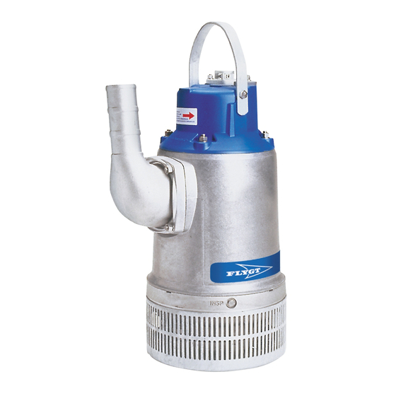
Page 14: Product Description
Number of holes Hole dimensions 6×50 mm (0.24× 1.96 in.) For more information about the strainer, see Dimensions and weights (page 46). Pressure class Medium head High head Super head Impeller type Wear resistant 2125 Installation, Operation, and Maintenance Manual... -
Page 15: Monitoring Equipment
17. Duty class 18. Duty factor 19. Product weight 20. Locked rotor code letter 21. Power factor 22. Maximum ambient temperature 23. Read installation manual 24. Notified body/only for EN-approved Ex-products Figure 1: The data plate 2125 Installation, Operation, and Maintenance Manual... -
Page 16: The Ex Approval Plate
The sales denomination consists of the four-digit sales code and two letters that indicate the hydraulic end and type of installation. This is an example of a sales denomination, and an explanation of its parts. NP 3085 Hydraulic part Installation type Sales code 2125 Installation, Operation, and Maintenance Manual... - Page 17 The serial number is used for identification of an individual product, and is divided into four parts. This is an example of a serial number, and an explanation of its parts. NP 3085.183 - 951 0163 Product code Production year Production cycle Running number 2125 Installation, Operation, and Maintenance Manual...
-
Page 18: Installation
For more permanent installations with a heavily contaminated pumped liquid, a settling pump-sump is recommended. Figure 2: Settling pump-sump Discharge line requirements The discharge line can be run vertically or horizontally, but must be without sharp bends. 2125 Installation, Operation, and Maintenance Manual... -
Page 19: Fasteners
5. Connect the motor cable and the starter and monitoring equipment according to the separate instructions. Make sure that the impeller rotation is correct. For more information, see Check the impeller rotation (page 27). 2125 Installation, Operation, and Maintenance Manual... -
Page 20: Make The Electrical Connections
• The cables must be in good condition, not have any sharp bends, and not be pinched. • The sheathing must not be damaged and must not have indentations or be embossed (with markings, etc.) at the cable entry. 2125 Installation, Operation, and Maintenance Manual... -
Page 21: Earthing (Grounding)
5. Make sure that any thermal contacts incorporated in the pump are properly connected to the terminal board. 6. Install the cover. 7. Fasten the screws on the entrance flange so that the cable insertion assembly bottoms out. 8. Tighten the clamping screws. 2125 Installation, Operation, and Maintenance Manual... -
Page 22: Cable Charts
Colors and marking of the mains leads Mains SUBCAB 7GX SUBCAB 4GX SUBCAB AWG SUBCAB Screened Black 1 Brown Brown Black 2 Black Black Black Black 3 Grey White Grey Black 4 Black 5 Black 6 2125 Installation, Operation, and Maintenance Manual... - Page 23 SUBCAB 4GX White T1 Orange White T1 White T2 Blue White T2 White T3 White T4 Colors of the stator leads Stator connection Lead color Green Green Brown Blue Brown Blue Yellow Black Yellow Black 2125 Installation, Operation, and Maintenance Manual...
- Page 24 U1 W2 V1 U2 W1 V2 W1 V2 W1 V2 Y connection D connection T1 T2 T1 T2 SUBCAB ® SUBCAB ® SUBCAB ® SUBCAB ® T1 T2 T1 T2 T1 T2 T1 T2 V1 U2 2125 Installation, Operation, and Maintenance Manual...
- Page 25 SUBCAB 4GX / SUBCAB AWG, 6 stator leads, Y and D connection (terminal board and contactor unit) Y connection D connection ® ® SUBCAB SUBCAB L1 L3 L2 L1 L3 L2 W2 U1 W1 V2 W2 U1 V1 U2 W1 V2 2125 Installation, Operation, and Maintenance Manual...
- Page 26 T16 T15 T2 T1 U1 U5 V1 V5 W1 W5 T16 T15 T2 T1 U1 U5 V1 V5 W1 W5 W5 W2 V2 U2 Stator leads W2, U2, and V2 are connected together on the terminal. 2125 Installation, Operation, and Maintenance Manual...
- Page 27 SUBCAB 4GX / SUBCAB AWG, 60 Hz only, 12 stator leads, Y serial and Y parallel connection Stator leads W6, U6, and V6 are connected together in an insulated closed-end splice. Y serial connection (460 V) Y parallel connection (230 V) ® SUBCAB ® SUBCAB ® ® SUBCAB SUBCAB 2125 Installation, Operation, and Maintenance Manual...
- Page 28 7x1.5 7Gx ___ ® SUBCAB T1 T2 T1 T2 T16 T15 T2 T1 U1 W2 V1 U2 W1 V2 W1 V2 SUBCAB 7GX, 6 stator leads, Y/D connection (terminal board and contactor unit) SUBCAB 2125 Installation, Operation, and Maintenance Manual...
-
Page 29: Check The Impeller Rotation
• If the motor has a 3-phase connection, then transpose two phase conductors and repeat this procedure from step 1. For 3-phase pumps with external starters or without built-in motor protection, the phases must be shifted on the output terminal of the starter. 2125 Installation, Operation, and Maintenance Manual... -
Page 30: Operation
NOTICE: Make sure that the rotation of the impeller is correct. For more information, see Check the impeller rotation. 1. Check the oil level in the oil housing. 2125 Installation, Operation, and Maintenance Manual... -
Page 31: Clean The Pump
Let the pump run for a while in clean water, or flush it through the discharge connection. 2125 Installation, Operation, and Maintenance Manual... -
Page 32: Maintenance
5.4 (4) 9.3 (6.9) 22 (16) 44 (32) 76 (56) 187 (138) 364 (268) 629 (464) 1240 Nm (ft- (915) lbs) Carbon steel and alloyed steel Property class 70 is torque tightened as class 80. 2125 Installation, Operation, and Maintenance Manual... -
Page 33: Service
NOTICE: Shorter intervals might be required for tough operating conditions such as very abrasive and corrosive applications and media (liquid) temperatures >40°C. Inspection Regular inspection and service of the pump ensures more reliable operation. 2125 Installation, Operation, and Maintenance Manual... - Page 34 Repair or replace any damaged equipment. equipment Clean and adjust the equipment. Regardless of individual applications, the inspection chamber should not be inspected less frequently than the intervals for normal applications and operating conditions at media (liquid) temperatures <40°C. 2125 Installation, Operation, and Maintenance Manual...
-
Page 35: Major Overhaul
The oil housing may be pressurized. Hold a rag over the oil plug to prevent oil from spraying out. 3. Turn the pump so that the oil hole faces downwards and let the oil run out. 2125 Installation, Operation, and Maintenance Manual... -
Page 36: Fill With Oil
Tightening torque: 10–40 Nm (7.4–30 ft-lbs) Replace the impeller Remove the impeller WARNING: A worn impeller and/or pump housing can have very sharp edges. Wear protective gloves. 1. Lay the pump on its side. 2125 Installation, Operation, and Maintenance Manual... - Page 37 2. Remove the items in the illustrations: a) Remove the nuts and the strainer. b) Remove the nuts and the suction cover. c) Remove the nuts and the diffuser. 3. Remove the impeller: a) Lock the impeller to prevent rotation. 2125 Installation, Operation, and Maintenance Manual...
-
Page 38: Install The Impeller
2. Install the impeller: a) Fit the impeller onto the shaft. b) Lock the impeller to prevent rotation. Use pliers, screwdriver, or similar. c) Tighten the impeller nut. Tightening torque: 60 Nm (44 ft-lbs). 2125 Installation, Operation, and Maintenance Manual... - Page 39 Place the nuts on the studs. Tighten the nuts evenly all around. 6. Check that the impeller can rotate easily. 7. Install the strainer. In order for the pump to perform at maximum capacity, the impeller must be adjusted regularly. 2125 Installation, Operation, and Maintenance Manual...
-
Page 40: Troubleshooting
• All fuses have power and that they are securely fastened to the fuse holders. • The overload protection is not tripped. • The motor cable is not damaged. The impeller is stuck. Clean: 2125 Installation, Operation, and Maintenance Manual... -
Page 41: The Pump Does Not Stop When A Level Sensor Is Used
• Whether the voltage drop in the line at the starting surge causes the contactor's self-holding malfunction. If the problem persists, contact the local Xylem service shop. Always state the serial number of your pump when you contact Xylem, see Product Description (page 12). 2125 Installation, Operation, and Maintenance Manual... -
Page 42: The Pump Runs But The Motor Protection Trips
(page 12). The pump delivers too little or no water WARNING: Always disconnect and lock out power before servicing to prevent unexpected startup. Failure to do so could result in death or serious injury. 2125 Installation, Operation, and Maintenance Manual... - Page 43 • Depending on the installation type, add a means for priming the pump, such as a foot valve. If the problem persists, contact the local Xylem service shop. Always state the serial number of your pump when you contact Xylem, see Product Description (page 12). 2125 Installation, Operation, and Maintenance Manual...
-
Page 44: Technical Reference
±10%, provided that it does not run continuously at full load overheating Voltage imbalance tolerance Stator insulation class H (180°C [360°F]) Specific motor data Version code 181: 3-phase, 50 Hz Motor type: • 2,890 rpm • Rated output 8.0 kW (11 hp) 2125 Installation, Operation, and Maintenance Manual... - Page 45 230 D 230 Y parallel 260 D 380 D 380 Y 400 Y 440 D 440 Y 440 Y serial 460 D 460 Y 460 Y serial 480 D 575 D 600 D 1100 Y 2125 Installation, Operation, and Maintenance Manual...
- Page 46 440 Y serial 460 D 460 Y 460 Y serial 575 D 600 D 1100 Y Version code 051: 3-phase, 60 Hz Motor type: • 3,485 rpm • Rated output 9.7 kW (13 hp) 2125 Installation, Operation, and Maintenance Manual...
- Page 47 Rated current (A) Starting current (A) 220 Y parallel 230 Y parallel 260 D 380 D 440 D 440 Y 440 Y serial 460 D 460 Y 460 Y serial 575 D 600 D 1100 Y 2125 Installation, Operation, and Maintenance Manual...
-
Page 48: Dimensions And Weights
Technical Reference Dimensions and weights All measurements in the illustrations are in millimeters, if not otherwise specified. Figure 4: Version code: 181 HT 2125 Installation, Operation, and Maintenance Manual... - Page 49 Technical Reference Figure 5: Version code: 320 HT 2125 Installation, Operation, and Maintenance Manual...
- Page 50 Technical Reference Figure 6: Version code: 320 MT 2125 Installation, Operation, and Maintenance Manual...
- Page 51 Technical Reference Figure 7: Version code: 051 HT 2125 Installation, Operation, and Maintenance Manual...
-
Page 52: Performance Curves
Technical Reference Figure 8: Version code: 690 SH Performance curves Standard Pumps are tested in accordance with ISO 9906, HI level A. 2125 Installation, Operation, and Maintenance Manual... - Page 53 Technical Reference 2125.181 P [kW] H [m] Q [l/s] Figure 9: 50 Hz 2125 Installation, Operation, and Maintenance Manual...
- Page 54 Technical Reference [hp] / [kW] H [ft] / [m] 10 12 14 16 18 Q [l/s] / [usgpm] Figure 10: 60 Hz 2125 Installation, Operation, and Maintenance Manual...
- Page 55 Technical Reference 2125.320 P [kW] H [m] Q [l/s] Figure 11: HT, 50 Hz 2125 Installation, Operation, and Maintenance Manual...
- Page 56 Technical Reference [hp] / [kW] H [ft] / [m] Q [l/s] / [usgpm] Figure 12: HT, 60 Hz 2125 Installation, Operation, and Maintenance Manual...
- Page 57 Technical Reference P [kW] H [m] Q [l/s] Figure 13: MT, 50 Hz 2125 Installation, Operation, and Maintenance Manual...
- Page 58 Technical Reference [hp] / [kW] H [ft] / [m] 0 100 200 300 400 500 600 700 800 900 Q [l/s] / [usgpm] Figure 14: MT, 60 Hz 2125 Installation, Operation, and Maintenance Manual...
- Page 59 Technical Reference 2125.690 P [kW] H [m] Q [l/s] Figure 15: HT, 50 Hz 2125 Installation, Operation, and Maintenance Manual...
- Page 60 Technical Reference [hp] / [kW] H [ft] / [m] Q [l/s] / [usgpm] Figure 16: HT, 60 Hz 2125 Installation, Operation, and Maintenance Manual...
- Page 61 Technical Reference P [kW] H [m] Q [l/s] Figure 17: MT, 50 Hz 2125 Installation, Operation, and Maintenance Manual...
- Page 62 Technical Reference [hp] / [kW] H [ft] / [m] 0 100 200 300 400 500 600 700 800 900 Q [l/s] / [usgpm] Figure 18: MT, 60 Hz 2125 Installation, Operation, and Maintenance Manual...
- Page 63 Technical Reference P [kW] H [m] Q [l/s] Figure 19: ST 2125 Installation, Operation, and Maintenance Manual...
- Page 66 Visit our Web site for the latest version of this document and more information Gesällvägen 33 174 87 Sundbyberg The original instruction is in English. All non-English instructions are translations of the original instruction. Sweden Tel. +46-8-475 60 00 © 2011 Xylem Inc Fax +46-8-475 69 00 http://tpi.xyleminc.com 898401_1.0_en.US_2009-12_IOM.2125.051/.181/.320/.690_XR...
Need help?
Do you have a question about the 2125 and is the answer not in the manual?
Questions and answers
looking for the pump curve 2125 180