Advertisement
Advertisement
Table of Contents

Related Manuals for Protek 3003B

Summary of Contents for Protek 3003B
-
Page 5: Controls And Indicators
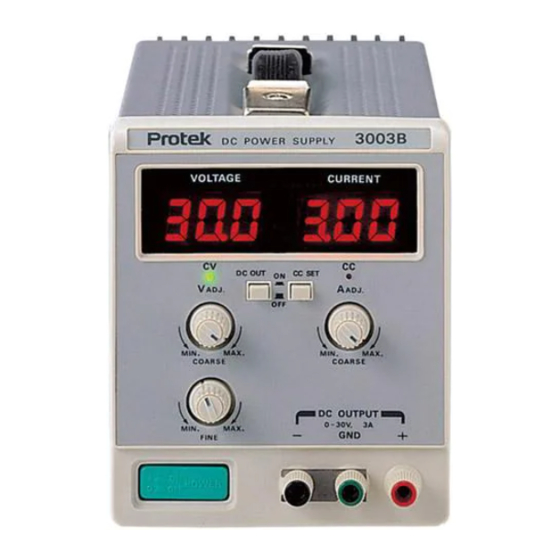
1. DESCRIPTION CONTROLS AND INDICATORS ①. POWER SWITCH: on/off switch. ②. OUTPUT TERMINAL: positive polarity (+) is red, negative polarity (-) is black, earth and chassis ground is green. ③. DIGITAL VOLT METER: indicates the output voltage. ④. DIGITAL CURRENT METER: indicates the output current. ⑤. -
Page 6: Specification
2. SPECIFICATION MODEL 3003 3005 3006 3015 3032 3033 Output DC voltage 0-30V 0-30V 0-60V 0-30V 0-30V 0 - 30V Output DC current 0-3A 0-5A 0-1.5A 0-1.5A 0 - 3A 0 - 1.5A DUAL DUAL DUAL 5V, 5A FIXED ≤ 0.02% + 2mV Load Regulation (Load Effect) ≤... -
Page 7: Turn-On Checkout Procedure
3. OPERATION WARNING: Before connecting line power to your power supply, make sure that the AC input voltage is correct for your power source. TURN-ON CHECKOUT PROCEDURE. a) Turn A-adj control fully counter clockwise. b) Set AC power switch push to on position, digital display and CV lamp should light. c) Turn VOLTAGE controls fully counter clockwise to ensure that output decreases to OV dc then fully clockwise to ensure that output voltage increase to the maximum output voltage. -
Page 8: Constant Current Operation
CONSTANT CURRENT OPERATION To set up a power supply for a constant current operation, proceed as follows: a) Turn A-adj control fully counter clockwise to ensure that output decreases to 0 A, and then on power supply. b) Adjust V-adj control (no load connected) for maximum output voltage allowable(voltage limit), as determined by load conditions. -
Page 9: Maintenance
4. MAINTENANCE WARNING: The following instructions are for use by qualified personnel only. To avoid electrical shock, do not perform any servicing other then contained in the operating instructions unless you are qualified to do so. Fuse Replacement If the AC fuse blows, the CV or CC lamp will not light and the power supply will not operate. If the DC fuse blows, the CV or CC lamp and digital display is light but DC OUTPUT will not operate. -
Page 10: Calibration Adjustment
5. CALIBRATION ADJUSTMENT ADJUSTMENT OF THE RATING VOLTAGE. Connect digital multimeter across output terminals of supply and set the DC volt position. b) Turn on supply and push on DC OUT push button switch. Adjust voltage controls (COARSE, FINE) fully clockwise. d) Adjust S203 for a reading of rate volts x 1.05 on the digital multimeter.
Need help?
Do you have a question about the 3003B and is the answer not in the manual?
Questions and answers