
Related Manuals for RepRap Prusa i3


Summary of Contents for RepRap Prusa i3
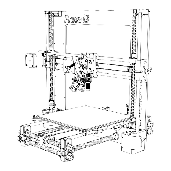
- Page 1 Documentation version 1.1.16 Prusa i3 Rework USER GUIDE REV 1.5 Document Version 1.1.16...
-
Page 2: Introduction
Prupose a visual guide of the differents steps to build and use a • Licences : Prusa i3 Rework. Prusa i3 : GPL 3.0 • Authors of this document This document : CC BY-NC-SA 4.0 http://creativecommons.org/licenses/by-nc-sa/4.0/ eMotion Tech – http://www.Reprap-France.com... -
Page 3: Table Of Contents
SUMMARY INTRODUCTION ANNEX Summary Adaptation of the Start G-code Printing of a piece with Repetier Host Driver and the firmware installation GCODE commands Maintenance Transfer of the firmware from Arduino Recommandations Connection to Repetier-Host Configuration and preset Checking endstop Invert motor’s direction Fan checking HEATED PARTS CHECKING Extruder... -
Page 4: Driver And The Firmware Installation
Driver and the firmware installation First : (1.0.6 version or lower). You can download it from our website or the official Arduino’s website. • Install the Arduino software After that, the RAMPS board must be connected on the Arduino board. •... - Page 5 • Run the Arduino software from the office. Selecting the card Arduino IDE launching Document Version 1.1.16...
- Page 6 Document Version 1.1.16...
-
Page 7: Transfer Of The Firmware From Arduino
Transfer of the firmware from Arduino • Open Arduino (file/open) the file of your USB drive: Prusa i3 Rework 1.5, and « Marlin.ino ». • Next, Click on Upload. Document Version 1.1.16... -
Page 8: Connection To Repetier-Host
Connection to Repetier-Host Connect the RAMPS board to the power supply 12v and respect polarity. Before to begin this tutorial, you have to get: • The electronic and mechanic parts (see the assembly instruc- tions); • The board need to be identified by your computer; •... - Page 9 Choice of the COM port Document Version 1.1.16...
- Page 10 Connect Repetier to your 3D printer by pushing on the button « Connect » Connexion à l'imprimante Check the message « idle » at the Bottom of the page. If you have waiting commands, it means that you have connection problem with your printer. Check the COM port and push on Reset button or reconnect the USB wiring.
-
Page 11: Configuration And Preset
/ 11 Configuration and preset Let start to a material checking on your machine. Manual moving of axis Push your carriage X and Y to the center of their axis, -if you feel resistance don’t force! -, You only need to unlocking your motors : Unblocking motors Unblocking of motors Document Version 1.1.16... -
Page 12: Document Version 1
For Z axis, move up the extruder for at least 20 mm above the PCB heatbed by turning the two couplers at the same time. Be sure that axis X stay horizontal to not damage plastic piece. Now you are ready to move safely. Document Version 1.1.16... -
Page 13: Checking Endstop
/ 13 Checking endstop To know if your endstop is functional, connect them and check that the red LED switch on when you do a contact. Emergency stop button Document Version 1.1.16... - Page 14 Press the X homing and check the X carriage stop to move after touching the endstop X. If there is a problem you can press on the emergency stop button to stop motors. Repeat the operation for Y axis. For Z axis, we will explain the prober in the fifth parts (« using of the paper »). Moving command axis X and Y homing Document Version 1.1.16...
-
Page 15: Invert Motor's Direction
/ 15 Invert motor’s direction Disconnect Repetier Host and all power sources (power supply 12V and USB).Then invert your motor plug on the RAMPS card. Reconnect your machine. Repeat the operation for Y and Z axis. For Z axis the positive direction means a vertical rise. -
Page 16: Heated Parts Checking
PCB heatbed and cartridge heater checking Extrusion Launch the heating of the cartridge heater: Check if the motor turn in the good direction (do not set up the filament). Use manual commands to extrude 10 mm: Note : extruder’s temperature will progressively increase to the targe- ted temperature (here 200°C). -
Page 17: Extruder
/ 17 If it is necessary, invert the direction connection of the motor connector on Cut the filament extremely beveled to RAMPS board. insert easily your filament in the extru- Push Launch the heating according to the sort of plastic filament: For PLA : from 200°... -
Page 18: Using Z Sensor
Using Z Sensor The inductive sensor will allow you to automatically palpate 4 calibration points to correct mounting imperfections. This only detects metals (detection ~ 1mm for non-ferrous metals (aluminum, ...) and ~ 3mm for ferrous metals (steel, cast iron, ...). Caution: use of a glass plate is prohibited with the use of the bed of aluminum. -
Page 19: Checking The Sensor
/ 19 Step 2 : checking sensor operation View the feedback (logs) : Position a metal object in your sensor and type «M119» in the command prompt of «manual control» tab. Press this button to make visible This button displays Repetier’s the log Visibility button logs Type of response expected in the logs:... -
Page 20: Balancing Z Motors
Step 2 : Balancing Z motors To reduce the correction of the auto-leveling, it is highly advisable to balance the height difference between the two Z motors. With the power supply off, push the X carriage to the endstop and turn the coupler until your heating nozzle touches the bed: Left : Then, right : Step 3 : Adjusting motor power... -
Page 21: Z-Axis Calibration
/ 21 Step 4 : Z-Axis calibrating What is the target ? To properly calculate the correction of the auto-leveling we need to determine the difference of our printhead with the heating bed when palpated with our sensor. Note: This difference is therefore a negative value beacause it will lower the heating head of measurement recorded up to get the point Z = 0. - Page 22 5 - Type the «G92 Z0» command to set the point Z = 0 of your printer 6 - Using the arrows, move your Z axis 30mm upward, so you will be at Z = 30 7 - Type the «G30» command to perform a probe and detect your metal bed 8 - Here is a typical example of a response in your logs: Note: For this example, we just measure a difference of 0.49mm from our printhead 9 - To set the value of the specified gap type the following command :...
-
Page 23: Auto-Leveling
/ 23 Auto-leveling The «G29» command launches probe of four calibration points. It is strongly recommended to do an initialization of the machine in the manual control before this command (or type the command «G28»). The «M500» command save the calibration in the memory of your printer: M500 Document Version 1.1.16... -
Page 24: Annex
ANNEX ANNEX Document Version 1.1.16... -
Page 25: Adaptation Of The Start G-Code
/ 25 ANNEX Adaptation of the Start G-code Go in the tab « Slicer » and select the slicer « Slic3r ». Next click on « configuration », and go in the tab « Printer Settings », click on « Custom G-code ». After that, write in « Start G-code » the command below : Document Version 1.1.16... - Page 26 ANNEX Copy paste the following sequence : G91 ; using relative distance G1 Z20 ; go to position Z 20 G90 ; absolute positioning G28 ; X, Y and Z homing G29 ; Auto leveling M500; save to EEPROM Document Version 1.1.16...
-
Page 27: Printing Of A Piece With Repetier Host
/ 27 ANNEX Printing of a piece with Repetier Host We will first choose a 3D model to print. We suggest you to start with a simple object like the «Y Motor», with a fairly large plate surface to be able to observe the printing of the first layer (decisive) as comfortable as possible. IYou can also go to the Thingiverse website and find a simple object to print (cube or another simple objet without difficulty). - Page 28 ANNEX Select the tab « Slicer » and do the follow actions : Note: We will only detail the main parameter of slicing. Document Version 1.1.16...
- Page 29 / 29 ANNEX Infill settings Document Version 1.1.16...
- Page 30 ANNEX Speed settings Saving of « Filament Settings » Document Version 1.1.16...
- Page 31 / 31 ANNEX Filament settings Saving of « Filament Settings » Document Version 1.1.16...
- Page 32 ANNEX Extruder settings Saving of « Printer Settings » Document Version 1.1.16...
- Page 33 / 33 ANNEX Slice : The slice transform a virtual polygonal meshed body into machine coordinates, It take several seconds (depend of the size and the complexity of the piece). You can follow the progression of the slice. Document Version 1.1.16...
- Page 34 ANNEX When the slice is finished, you are automatically send on preview’s tab. Document Version 1.1.16...
- Page 35 / 35 ANNEX Piece drawn in machines’ path Document Version 1.1.16...
- Page 36 ANNEX Now you can start the print : Congratulation for your first print !! Document Version 1.1.16...
-
Page 37: Gcode Commands
/ 37 ANNEX Ccommandes GCODE G1 : linear motion (ex : G1 X100 Y100 F3000) G28 : back to home (ex : G28 X Y) M500 : save l’EEPROM M851 : define «Z Probe Height» value (ex : M851 Z-0.49) M999 : restart printer G29 : inductive probe at actual place G30 : inductive probe at plate’s corners... -
Page 38: Maintenance
Troubleshooting : A FAQ is available for the Prusa i3 Rework 1.5 on our website in the «Support» section, do not hesitate to consult it if you are having trouble with your machine, most failures are resolved through this tool, do not deprive yourself ! - Page 39 / 39 ANNEX CONGRATULATION ! Your first print is a success ! Document Version 1.1.16...
- Page 40 ANNEX Thank you for choosing Prusa i3 Rework rev. 1.5 www.reprap-3d-printer.com Document Version 1.1.16...
Need help?
Do you have a question about the Prusa i3 and is the answer not in the manual?
Questions and answers