Table of Contents
Advertisement
Quick Links
Download this manual
See also:
Owner's Manual
Advertisement
Table of Contents

Related Manuals for STEINWAY LYNGDORF C


Summary of Contents for STEINWAY LYNGDORF C
- Page 1 MODEL C INSTALLATION MANUAL VERSION 2.0 [Skriv tekst]...
-
Page 2: Table Of Contents
TABLE OF CONTENTS TABLE OF CONTENTS ..................2 INTRODUCTION ....................3 COMPLIANCE ....................3 INTRODUCTION TO THE MODEL C MUSIC SYSTEM ........4 UNPACKING MODEL C MUSIC SYSTEM ............6 SYSTEM PLACEMENT IN THE ROOM ..............9 ASSEMBLY OF MODEL C MUSIC SYSTEM ........... 10 USER INTERFACE MODEL C MUSIC SYSTEM..........16 MODEL C SOFTWARE PROGRAMMING ............ -
Page 3: Introduction
Steinway Lyngdorf products and accessories comply with parts 15 and 68 of the FCC rules. Operation is subject to the following two conditions: (1) this device may not cause harmful interference; and (2) this device must accept any interference received, including any interference that may cause undesired operation. -
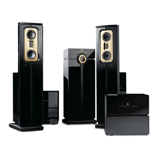
Page 4: Introduction To The Model C Music System
Preparing for Cabling Steinway Lyngdorf Model C Music System has two pieces of 10 meters (33 feet) of CAT-5E link cable and four pieces of 1.8 meter (6 feet) power cable included in the accessory pack. -
Page 6: Unpacking Model C Music System
UNPACKING MODEL C MUSIC SYSTEM Pull out the Clip-Lok opening tool by using two fingers. Place the tool behind the clip. Use your other hand to keep the clip in place when you unlock it. Otherwise the clip may cause damage when it springs out of grip. - Page 7 Unlock the Clip-Lok clips following the instructions on page 8 and the dolly can be taken out of the crate. Unpacking the Model C Head Unit The head unit must be unpacked in the same way as the speakers. Remove the Clip-Lok clips from the top of the crate and remove the lid.
- Page 8 Depending on the remaining power level in the batteries, a full charging may require 3-4 hours. Charge the remote control while you install the Model C Music System! The System INSTALLATION FORM in the Manual must be SIGNED by the installer, or the factory...
-
Page 9: System Placement In The Room
Both speakers should have the same amount of side reflections, i.e. symmetrical positions in the room relative to adjacent walls. • The Model C Music System has a time delay adjustment procedure to compensate for unsymmetrical placements of the speakers compared to the listening position. See Speaker Delay section. -
Page 10: Assembly Of Model C Music System
12 pieces of 48 mm high spikes for floors covered by thick carpet. c. 12 pieces of non-penetrating feet mainly for marble, granite or similar floor materials. Spikes are the most stable option but might cause damage to the floor below; therefore, the use of spikes will be each customer’s own responsibility. - Page 11 Installation of Amplifier Modules into the Speakers The amplifier modules are located in sealed compartments in the loudspeaker crates as illustrated. Remove the Clip-Lok clips with care as described on page 8 to avoid any damage when they are unleashed. The amplifier modules must be installed in their compartments on the speaker stands and wired prior to operation.
- Page 12 Carefully slide the amplifier module inside (photo below). Then fasten the top of the module to the cabinet with the two M6 bolts that you previously removed. Cable Connections Between Amplifier Module and Loudspeaker After assembly of the electronics box, the three speaker cables must be connected to the amplifier module as follows: 1.
- Page 13 Link Wiring of System The Model C Music System is connected by a proprietary Steinway Lyngdorf link. The link cable will carry both the digital audio signal and the control signals. It is very important that only CAT-5E cables and RJ-45 connectors approved by Steinway Lyngdorf are being used. Poor quality cables and plugs represent a major risk of noise and interference problems and may even cause violation of safety and EMC regulations.
- Page 14 Installation Menu. Connecting the Power Cables DO NOT power up Model C before you have read the power-up sequence instruction on the next page! When all signal connections have been properly made, you can connect the Model C to the mains power.
- Page 15 Powering up the System IMPORTANT! The first power up sequence after final assembly of the system can only be performed in one way: 1. Speakers first. 2. Turn on head unit after speaker activation. The head unit must be able to identify the speakers connected to it by the link network. This will happen automatically when the head unit is activated.
-
Page 16: User Interface Model C Music System
USER INTERFACE MODEL C MUSIC SYSTEM Model C Head Unit Display and User Interface The volume control display indicates the level on a scale from 0.0 to 99.9. It also shows muting when activated and CD track information briefly when you skip or search. When RoomPerfect™ is activated the logo will be displayed. -
Page 17: Model C Software Programming
MODEL C SOFTWARE PROGRAMMING Finding the Installation Menu The basic programming of the Model C Music System must be performed via the Installation Menu in the head unit display. This Installation Menu is not accessible from the ordinary User Menu. To... - Page 18 Speaker Delay Settings The Speaker Delay menu is used for adjusting delays in setups with more than two speakers or setups where speakers are placed asymmetrically as seen from the listening position. In a standard setup with two speakers placed symmetrically, there will be no need to change anything in the Speaker Delay menu.
- Page 19 Press ENTER for choice of entry. b. Spin the search wheel to search for letters and numbers. c. When the desired character is found, press SKIP FORWARD to store the character and move the cursor to the next position.
- Page 20 To adjust the sensitivity in decibel, spin the search wheel counterclockwise for decreasing and clockwise for increasing sensitivity. c. Press ENTER to store and exit each input. d. Repeat the procedure for each activated input. Then select the Exit menu item to return to the...
- Page 21 Default Volume When the Model C is activated the volume will automatically be set at the default level. The factory setting for volume level is 55 dB (relative to the maximum 99.9 dB). This setting may be changed by this procedure: a.
- Page 22 Adjust level by spinning the search wheel. c. Press ENTER to store the new setting and exit the menu. For jazz or popular music, a maximum volume setting of 92 dB is recommended in order to avoid any amplifier clipping or speaker overload. For classical music, where general recording levels are lower than for pop music, a higher setting might be necessary.
-
Page 23: Model C Roomperfect™ Calibration
Plug the supplied microphone cable into the microphone. c. Connect the microphone cable to the XLR microphone terminal on the rear panel of the head unit. d. Place the tip of the microphone itself in Focus Position 1 – the primary listening position. The microphone must be aligned so that the nozzle is positioned where the center of the listener’s head... - Page 24 Enter the RoomPerfect Menu in the display. b. Select Guided Measurement. c. Press ENTER to confirm and to commence the calibration process. The test signal will start and shortly thereafter the system will suggest an initial estimate of the desired maximum calibration volume (in dB), displayed as shown below.
- Page 25 RoomPerfect™ Focus Measurement Press ENTER to start the Focus position measurement. The display will ask you to place the microphone in the listening position. Press ENTER once more to commence the process. Each measurement has four steps: A low and a high frequency measuring signal, first in the left and then in the right channel.
- Page 26 RoomPerfect™ Room Measurements Now the room correction system will need to map the room as a whole. You must place the microphone in various room positions with random orientation in height and direction. These positions must be at least one meter (3.3 feet) away from the speakers. A minimum distance of 50 cm or 1.5 feet between the microphone positions is necessary.
- Page 27 this point, or any time later, you can decide whether the acquired room measurements are sufficient or you wish to add further room measurements to learn more about the room’s acoustical information. Adding more room measurements results in a higher RoomKnowledge, this in turn improves the room correction filters.
- Page 28 RoomPerfect™ Status In this submenu (last above) you will see how much the correction system knows about the room, and to which extent correction has been employed. RoomKnowledge is an index showing how many of the acoustical properties in a room have been mapped. The higher degree of knowledge, the greater the accuracy of the room correction.
-
Page 29: Roomperfect™ Troubleshooting
Solution: Raise the measuring signal volume before continuing with the measurement, or reduce the noise from the environment. The Model C Music System will show an error message (-E-) in the volume display in case of speaker related problems. - Page 30 RoomPerfect™ troubleshooting WARNING: The microphone is a very sensitive and calibrated device. Treat it with utmost care. If the microphone has been dropped on the floor, or otherwise maltreated, it may have been damaged. Contact Steinway Lyngdorf for a replacement before final system calibration!
-
Page 31: Reset, Integration, Handing Over To Owner
Connect the supplied Remote Interface Box to, for instance, the Crestron system and to mains power. c. The MAC address of the interface box will be displayed. The system will ask if you wish to add it. Confirm this. - Page 32 To avoid damage to the lacquer, you must only use the original protective factory foil which you can obtain from Steinway Lyngdorf. If shipping by forwarder is necessary, you will need Tip’N’Tell and Shockwatch indicators, which are also available from Steinway Lyngdorf.
-
Page 33: Trademarks
TRADEMARKS DTS is a registered trademark & the DTS logos and Symbol are trademarks of DTS, Inc. Manufactured under license under U.S. Patent #’s: 5,451,942; 5,956,674; 5,974,380; 5,978,762; 6,226,616; 6,487,535 & other U.S. and worldwide patents issued & pending. DTS is a registered trademark and the DTS logos, Symbol, DTS-HD Master Audio are trademarks of DTS, Inc. -
Page 34: Service Information
SERVICE INFORMATION In order to obtain warranty service you must contact your original dealer or the Steinway Lyngdorf distributor of the region or country where you are located. If you have trouble locating an authorized representative, please contact the Steinway Lyngdorf Customer Service Department using the contact information at www.steinwaylyngdorf.com, or you may email service@steinwaylyngdorf.com.
Need help?
Do you have a question about the C and is the answer not in the manual?
Questions and answers