
Related Manuals for eSSL inBIO460 Series

Summary of Contents for eSSL inBIO460 Series
- Page 1 Security at Fingertips User Manual Installation Guide for inBIO460 Series Access Control Panel www.esslsecurity.com...
- Page 2 Product Overview inBIO460 InBio carries out the matching of fingerprints on the panels. The FR Series of readers transmit fingerprint templates to InBio via RS-485 for fast and accurate matching with templates stored in a data-base. InBio controllers install easily on your network and support both TCP/IP and RS-485 communication.
-
Page 3: Table Of Contents
Table of Contents 1. Important Security Instructions ............1 1.1 Important Security Instructions ..........1 1.2 Installation Cautions ..............3 2. Introduction ..................5 2.1 System Function Parameters............5 2.2 Product Technical Parameters............6 2.3 Indicators Description..............6 3. Connection and Installation ..............8 3.1 Panel Box Installation..............8 3.2 Installation and Wiring ..............9 3.3 System Structure..............10 3.4 Connection Terminals ..............12... -
Page 4: Important Security Instructions
1. Important Security Instructions 1. Important Security Instructions 1.1 Important Security Instructions 1. Read, follow and keep instructions: Before operating the equipment, read and follow strictly all security and operation instructions. Please keep the instructions for reference. 2. Accessories: Please use the accessories recommended by the manufacturer or delivered with the product. - Page 5 Installation Guide for inBIO460 Series Control Panel The equipment is wetted or exposed to bad weather (rain, snow, etc.). If the equipment cannot work normally even though operated as instructed, please be sure to adjust only the control components specified in the operation instructions.
-
Page 6: Installation Cautions
1. Important Security Instructions 1.2 Installation Cautions 1. All wires must run through casing pipes, for example PVC or galvanized pipes, to prevent failure caused by rodent damage. Although a control panel is designed with good antistatic, lightning-proof, and leakage-proof functions, ensure its chassis and the AC ground wire are connected properly and the AC ground wire is grounded physically. - Page 7 Installation Guide for inBIO460 Series Control Panel 11. In inBIO reader connection, if the reader shares the power with the control panel, it is recommended that the wire should be less than 100 meters. If you need to use in the longer distance, please use the separate power supply.
-
Page 8: Introduction
2. Introduction 2. Introduction The access control management system is a new modernized security management system, which is an effective measure for security and protection management. It is mainly used to manage entrances and exits of important places, such as banks, hotels, equipment rooms, offices, smart communities, and factories. -
Page 9: Product Technical Parameters
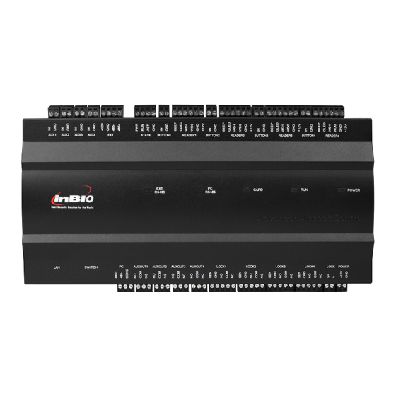
Installation Guide for inBIO460 Series Control Panel 2.2 Product Technical Parameters Working power supply: Rated voltage 12V (±20%) DC; rated current ≤0.5A. Working environment: Temperature 0°C-55°C; humidity 10%-80%. Output load: Working voltage AC ≤ 30V, rated current ≤ 8A; DC ≤ 36V, rated current ≤... - Page 10 2. Introduction 4. PC RS485 indicator (yellow & green): Flash state indicates it is sending or receiving data through RS485 communication; 5. CARD indicator (yellow): Flash state indicates card is punched on reader. See the indicators in the following figure: Indicators in the inBIO460...
-
Page 11: Connection And Installation
3. Connection and Installation 3. Connection and Installation 3.1 Panel Box Installation Installation steps for the control panel: Appearance and Internal of the panel box:... -
Page 12: Installation And Wiring
3. Connection and Installation 3.2 Installation and Wiring Access Control Panel Wire Installation Notes: 1. Before connection, make sure the power supply is disconnected. Any operation with power connected will cause severe damage to the equipment. 2. The access control wires must be separated according to heavy and light current; the control panel wires, electronic lock wires, and exit button wires must run through their respective casing pipes. -
Page 13: System Structure
Installation Guide for inBIO460 Series Control Panel 3.3 System Structure inBIO460 System Structure Note: The diagram above takes the inBIO460 for example. By contrast, only one-door two-way access is applicable to the inBIO160 system; only... - Page 14 3. Connection and Installation two-door one-way or two-door two-way access is applicable to the inBIO260 system. The access control management system consists of two parts: Management workstation (PC) and control panel. They communicate via TCP/IP or RS485 networks. On a 485 bus, each management workstation can be connected with up to 63 inBIO control panels (preferably fewer than 32).
-
Page 15: Connection Terminals
Installation Guide for inBIO460 Series Control Panel 3.4 Connection Terminals inBIO160 terminal connection diagram:... - Page 16 3. Connection and Installation inBIO260 terminal connection diagram:...
- Page 17 Installation Guide for inBIO460 Series Control Panel inBIO460 terminal connection diagram:...
- Page 18 3. Connection and Installation Descriptions of the terminals: . The auxiliary input may be connected to infrared body detectors, fire alarms, smoke detectors, etc. 2. The auxiliary output may be connected to alarms, cameras, door bells, etc. 3. All the terminals mentioned above are set through relevant access control software.
-
Page 19: Connection With External Accessories
Installation Guide for inBIO460 Series Control Panel 3.5 Connection with External Accessories 1. Door sensor A door sensor is used to detect the open/closed status of a door. With a door sensor switch, an access control panel can detect illegal opening of a door, and will trigger an alarm. -
Page 20: Connection With Readers
3. Connection and Installation Connections between inBIO460 and external accessories Note: The diagram above takes inBIO460 for example. By contrast, inBIO160 provides one auxiliary input interface; inBIO260 provides two, and inBIO460 provides four. 3.6 Connection with Readers The control panel supports inBIO biometric verification reader and Wiegand reader. - Page 21 Installation Guide for inBIO460 Series Control Panel In use of inBIO reader, all operations including storage, verification, etc. execute in control panel. No need to re-register the fingerprints for reader changing. Realize the real biometric reader connection. 1. Connected with inBIO readers inBIO160 can connect two inBIO readers in the one-door two-way mode.
- Page 22 3. Connection and Installation inBIO260 provides four readers, which can be connected in the two-door two-way mode. inBIO460 provides four readers, which can be connected in the two-door two-way or four-door one-way mode. The Wiegand interfaces provided by the inBIO series can be connected to different types of readers.
-
Page 23: Relay Output Connection
Installation Guide for inBIO460 Series Control Panel 3.7 Relay Output Connection inBIO160 has two relays (by default, one used as a control lock and the other used as an auxiliary output); inBIO260 has four relays (by default, two used as control locks and the other two used as auxiliary outputs);... - Page 24 3. Connection and Installation we suggest changing the bigger one, such as 12V/5A. Except the power consumption reserved, there are 2A current for the lock. For the common electrical lock (the standby current is 300mA, the max current is 500mA), the max connected lock is 4.
- Page 25 Installation Guide for inBIO460 Series Control Panel 3. Dry mode: External power supply for NO Lock 4. Dry mode: External power supply for NC Lock...
- Page 26 3. Connection and Installation 5. Dry mode: NO Lock under the binary value control. 6. Dry mode: NC Lock under the binary value control.
- Page 27 Installation Guide for inBIO460 Series Control Panel...
-
Page 28: System Power Supply Structure
3. Connection and Installation 3.8 System Power Supply Structure An access control operator panel is powered by +12V DC. Generally, to reduce... - Page 29 Installation Guide for inBIO460 Series Control Panel power interference between control panels, each control panel should be powered separately. When high reliability is required, control panels and electronic locks should be powered respectively. To prevent power failure of a control panel from making the whole system unable...
-
Page 30: System Networking
4. System Networking 4. System Networking 4.1 System Wiring and Wires Requirements 1. RS485 communication wires are made of internationally accepted shielded twisted pairs, which provide effective protection and shield of interference. 2. The power supply is 12V DC converted from 220V. 3. - Page 31 Installation Guide for inBIO460 Series Control Panel In a building, distribution lines must be installed horizontally or vertically. They should be protected in casing pipes (like plastic or iron water pipes, to be selected according to the technical requirements of indoor distribution). Metal hoses are applicable to ceiling wiring, but must be secure and good-looking.
-
Page 32: Tcp/Ip Network Communication
4. System Networking 4.2 TCP/IP Network Communication The Ethernet 10/100Base-T Crossover Cable, a type of crossover network cable, is mainly used for cascade hubs and switches, or used to connect two Ethernet end-points directly (without a hub). Both 10Base-T and 100Base-T are supported. TCP/IP Communication System Networking 4.3 RS485 Network Communication RS485 communication wires are made of internationally accepted RVVP... -
Page 33: Dip Switch Settings
Installation Guide for inBIO460 Series Control Panel In inBIO reader connection, if the reader shares the power with the control panel, it is recommended that the wire should be less than 100 meters. If you need to use in the longer distance, please use the separate power supply. - Page 34 4. System Networking communication. The code is binary, and the lower places are in the front. When the switch is set to ON position, it indicates 1 (on); when the switch is set downwards, it indicates 0 (off). For example, to set a device number 39=1+2+4+32, which corresponds to the binary code 111001, put number 1, 2, 3, and 6 to ON position, as illustrated below.
- Page 35 Installation Guide for inBIO460 Series Control Panel...
- Page 36 4. System Networking 2. Restoring factory setting The silk-screened 7 (number 7) of the DIP switch is the switch for restoration of system settings. The switch is set to OFF by default. When it is moved upwards and downwards for three times within 10 seconds and finally returned to OFF position, the factory settings will be restored after the access control panel is restarted.
- Page 37 Installation Guide for inBIO460 Series Control Panel between 485+ and 485-.
- Page 38 #24,Shambavi Building, 23rd Main,Marenahalli, JP Nagar 2nd Phase, Bangalore - 560078 Phone: 91-8026090500 | Email : sales@esslindia.com www.esslsecurity.com...
Need help?
Do you have a question about the inBIO460 Series and is the answer not in the manual?
Questions and answers