Philips MCi500H Service Manual
Hide thumbs
Also See for MCi500H:
- Quick start manual (18 pages) ,
- Specifications (2 pages) ,
- User manual (46 pages)
Table of Contents
Advertisement
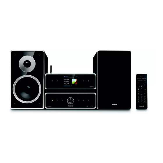
DVD Micro System
TABLE OF CONTENTS
Location of PCBS ............................................................ 1-1
Specifications ................................................................. 1-2
Measurement Setup ....................................................... 1-3
Service Aids, Safety Instruction, etc. .............................. 1-4
Instructions On CD Playability .............................. 1-5 to 1-6
Software & Firmware Upgrade .............................. 2-1...2-2
Malfuction Check Chart ( TBC) ......................................... 2-3
Service Test Program............................................. 3-1...3-2
.................................................. 4-1
Block Diagram ................................................................. 5-1
Wiring Diagram................................................................. 6-1
PB - AF/AMP....................................................................
Circuit diagram .................................................. 7-1...7-4
Layout diagram.................................................. 7-5...7-6
2008
DB 0824
PB - Aux IN....................................................................... 8-1
PB - Headphone .........................................................
PB - KEYS......................................................................
Circuit diagram .......................................................... 10-1
Layout diagram........................................................ 10-2
PB - KEYS & RC.............................................................
Circuit diagram .......................................................... 11-1
Layout diagram........................................................ 11-2
PB - LCD Interface.......................................................
PB - HasLi - 08 ................................................................ 13
Circuit diagram .............................................
7
Layout diagram........................................
Explode View ............................................................
Service Partlist ............................................................
MCi500H
9-1
10
11
12-1
13-1...13-9
13-10...13-11
14-1
14-2
3141 785 32960
Advertisement
Table of Contents

Related Manuals for Philips MCi500H


Summary of Contents for Philips MCi500H
-
Page 1: Table Of Contents
DVD Micro System MCi500H TABLE OF CONTENTS PB - Aux IN............... 8-1 Location of PCBS ............1-1 Specifications ..............1-2 PB - Headphone ............Measurement Setup ............1-3 PB - KEYS..............Service Aids, Safety Instruction, etc....... 1-4 Circuit diagram ............10-1 Instructions On CD Playability ...... -
Page 2: Location Of Pcbs
Location of PCBS SMPS Board TUNER MODULE WESLI-08 Board KEY Board AF & AMP Board VERSION VARIATIONS : Type /Versions: MCI500H Service policy Board in used: SMPS BOARD TUNER MODULE AF& BOARD AUX IN BOARD HEADPHONE BOARD KEYS&RC BOARD KEYS BOARD... -
Page 3: Specifications
Specification General HD player 230V ±10%, 50Hz (for /12, /05 /79) Frequency range ........30 -- 20,000Hz (-3dB) AC Power ..........120V ±10%, 60Hz (for /37) Signal-to-noise ratio ..........75dBA (IEC) .. 120V ±15%, 60Hz or 230V ±15%, 50Hz (for /55, /97) M4A (AAC) bit rate ...... -
Page 4: Measurement Setup
MEASUREMENT SETUP Tuner FM Bandpass LF Voltmeter 250Hz-15kHz e.g. PM2534 e.g. 7122 707 48001 RF Generator e.g. PM5326 S/N and distortion meter e.g. Sound Technology ST1700B Use a bandpass filter to eliminate hum (50Hz, 100Hz) and disturbance from the pilottone (19kHz, 38kHz). Tuner AM (MW,LW) Bandpass LF Voltmeter... - Page 5 SERVICE AIDS WARNING All ICs and many other semi-conductors are susceptible to electrostatic discharges (ESD). Careless handling during repair can reduce life drastically. When repairing, make sure that you are connected with the same potential as the mass of the set via a wrist wrap with resistance. Keep components and tools also at this potential.
-
Page 6: Instructions On Cd Playability
INSTRUCTIONS ON CD PLAYABILITY Customer complaint "CD related problem" Set remains closed! check playability playability ok ? For flap loaders (= access to CD drive possible) "fast" lens cleaning cleaning method is recommended check playability playability ok ? Play a CD for at least 10 minutes check playability playability... - Page 7 INSTRUCTIONS ON CD PLAYABILITY PLAYABILITY CHECK LIQUID LENS CLEANING Before touching the lens it is advised to clean the surface of the lens by blowing clean air over it. For sets which are compatible with CD-RW discs This to avoid that little particles make scratches on use CD-RW Printed Audio Disc ....7104 099 96611 the lens.
- Page 8 MCI500H Center. procedure. This information is also useful in case you Select HD mode, and then select Restore need to call Philips Customer Care Center. Register your Philips Wireless Music Center firmware with www.club.philips.com a.
- Page 9 ● Use your PC to register your product on If you are using a DHCP* enabled Access www.club.philips.com and go to "Show Point, Router or ADSL modem, the DNS Upgrades & Support" page to download and Gateway can be got automatically, so you Gracenote Music recognition database update.
-
Page 10: Service Test Program
3 - 1 3 - 1 SERVICE TEST PROGRAM To enter service mode,keep Display shows OK key depressed while Welcom to FSM plugging the main AC cord Ver: x.x Display shows Display shows HW Result 1.HW Test 111111 STOP STOP Display shows 2.LCD Test Press STOP key twice... - Page 11 3 - 2 3 - 2 SERVICE TEST PROGRAM Display shows Setting OK Setting Fail Display shows Display shows Display shows Display shows 5.FANControl Setting Deployed 5.1Full Speed 5.2FAN Off STOP Display shows Display shows Display shows Display shows Display shows 6.1Setting1 6.2Setting2 6.3Setting3...
-
Page 12: Disassembly Diagram
Disassembly Diagram 5. Remove Amp board 3. Remove Wesli board 1. Remove Left & Right Cabinet - Remove screws T3x6 - 1 pcs remove screws T3x6 - 4 pcs - Remove screws T3x6 - 4 pcs (Please refer to second picture) - Pull the left or right cabinet and then lift it. -
Page 13: Block Diagram
Block Diagram +9.1V +30V IC - AN18202A +9.1V +12V +9.1V Speakerbox FM-decoder Bass Incredible & & Surround Treble (9 Ohm) +9.1V filter synthesizer filter OSC out IC – TDA7468D Ripple Source Filter Selector TUNING Mute HAS-out R Powerup PANASONIC TM-10 V2TUNER-MODULE Stage Bass Engage... -
Page 14: Wiring Diagram
Wiring Diagram TM-10 7400 KEY & RC LCM 3.2’Color Yeboo 7400 2422 542 00048 / USA TSOP4836 2822 031 01522 2422 542 00049 / EU RC6 Receiver 314107803041 272217100648 PB 314107351023 08FMN-BTRK-A 8003 314107021631 430mm,10p,BD 8009 313911036061 100mm,8P,1mm BD 24FMN-BTRK-A LCM Interface Board 314107803011 24FMN-BTRK-A... -
Page 15: Pb - Af/Amp
PB - AF/AMP - Circuit Diagram - Sheet1 1103 E2 2202 B6 2203 E9 2204 C5 2206 B7 2505 D5 2506 D6 2507 D7 2511 B4 GND_A 2512 C4 2513 B3 2514 C3 2515 D5 2516 E5 2521 A4 3521 2521 +9.1V 2522 B4... - Page 16 PB - AF/AMP - Circuit Diagram - Sheet2 1101 F7 F207 B8 2212 C4 F208 B7 2213 A4 F209 D10 2214 H6 F210 F3 2215 C4 F211 F3 2216 C4 2217 A4 2218 A4 2223 D8 2234 D6 330n option 2235 B7 2924 2236 A10...
- Page 17 PB - AF/AMP - Circuit Diagram - Sheet3 1102 A9 5041 A4 1108 D1 5709 F8 1109 C1 5710 F8 1110 A1 6206 B7 1401 D9 7211 B8 RDS DECODER 1520 F4 7212 A7 1522 C5 7610 A3 5041 3244 3310 1523 D4 7611 B7...
- Page 18 PB - AF/AMP - Circuit Diagram - Sheet4 1104 C12 3421 F5 1403 D12 3422 F9 1404 E12 3424 F5 2207 A8 3425 F5 2282 A8 3426 G9 3400 5400 2400 A6 3429 G9 +AMP_1 2401 A7 3432 B8 2402 A8 3433 F8 2401 2406...
-
Page 19: Layout Diagram
PB - AF/AMP - Layout Diagram - TOP... - Page 20 PB - AF/AMP - Layout Diagram - Bottom...
-
Page 21: Pb - Aux In
PB - AUX IN 0002 D14 1201 B13 2204 E4 2207 D8 3203 B8 3206 C8 3209 E11 F203 B4 1200-1 B2 2202 B11 2205 E4 2208 E2 3204 B10 3207 C10 5202 B4 F204 C4 1200-2 D1 2203 C11 2206 E7 3202 B6 3205 C6... -
Page 22: Pb - Headphone
PB - HEADPHONE 0002 G4 1301 E2 2300 B6 2302 F7 3300 C11 5301 D10 5303 G8 F302 C5 F304 E6 1300 B9 1302 D14 2301 F6 2303 F9 5300 C10 5302 E10 F301 B5 F303 D7 F305 E5 a lug wire to ESD Metal Bracket F301 2300 1300... -
Page 23: Pb - Keys
10-1 10-1 PB - Keys - Circuit Diagram 1125 B2 1151 C6 1152 D6 1153 D6 1154 E6 1155 E6 1156 C7 1157 D7 1158 D7 52807-0810 1159 E7 600R 5103 F111 KEY_1 1160 F6 5104 600R F112 KEY_2 F113 1161 F6 GND_DAC GND_DAC... - Page 24 10-2 10-2 PB - Keys - Layout Diagram...
-
Page 25: Pb - Keys & Rc
11-1 11-1 PB - Keys&RC - Circuit Diagram 1401 H12 1403 E12 1405 G5 2400 C19 2402 D18 3401 D18 3403 D20 3405 F11 3407 E6 3409 F6 5400 C21 5402 E6 5404 F6 7400 C16 F402 E7 F404 E7 F406 E7 F408 F7 F410 C17... - Page 26 11-2 11-2 PB - Keys&RC - Layout Diagram...
-
Page 27: Pb - Lcd Interface
12-1 12-1 PB - LCD Interface 1606 F9 1620 G2 2601 E5 2603 F3 3601 D3 3603 D3 3611 B3 3613 B3 3615 C3 3617 C3 5600 E5 1614 F2 2600 D1 2602 E4 3600 C3 3602 D3 3604 D3 3612 B3 3614 C3 3616 C3... - Page 28 3140 470R F010 S_RCFAST_RDWR 3957 S_MPMC_WE_N S_MPMC_WE_N 3081-2 3118 USB/DOCK S_USB_BOOST 3956 S_MPMC_CKE S_MPMC_CKE 3081-3 3119 OPTION ECO_STBY 3955 100R 5036 S_MPMC_CLK CLKOUT 3954 S_MPMC_DYCS_N DYCS SPDIF-HDD/MUX / OPTION Ref. Des. MCi500H Ref. Des. 3078 3006 3087 3015 3022 3973...
-
Page 29: Pb - Hasli - 08
13-2 13-2 PB HasLI-08 - Circuit Digram - FLASH & SDRAM Part 0606 G5 2201 B5 2204 B6 2209 H3 2212 E9 3201-1 C6 3201-4 B6 3207 C6 3209-2 C6 3212 C3 3216 C6 3217-3 F5 3221-2 F5 3225-1 F5 3225-4 E5 3229-3 F5 3236 G3... - Page 30 13-3 13-3 PB HasLI-08 - Circuit Digram - mPCI & ATA Connector Part 1500-A C5 2500 A3 2521 D3 2525 F6 3502 C7 3506 C12 3511 C12 3516 E12 3521 C12 3525 C12 3529 D6 3533-1 F6 3534 F11 3539 D4 3543 E4 3548 G11 3552 E4...
- Page 31 13-4 13-4 PB HasLI-08 - Circuit Digram - I/O Interface Part 1107 G4 1609 B14 2613 C10 2618 B5 2623 B5 2629 F8 2634 C3 3021 C8 3615 C8 3631 D12 3633-1 A3 3634-2 B3 3662 H9 3671 G8 3679 C10 3684 G8 3689 G10 5604 B8...
- Page 32 13-5 13-5 PB HasLI-08 - Circuit Digram - AF Part 1705 A8 3770 B4 1706 G13 3771 C4 2703 A4 3772 C4 2704 B4 3773 D4 2705 D8 3774 D3 +2V7 iPOD ISOLATION(GND) / OPTION DIGITAL AUDIO OUTPUT / OPTION 2706 D10 3775 E3 2707 E7...
- Page 33 13-6 13-6 PB HasLI-08 - Circuit Digram - ETHERNET Part 1300 B11 F307 G2 1302 G2 F308 A11 2317 C5 2318 F6 2319 F7 2320 G5 5318 600R 2321 B11 5312 600R 2322 B12 +1V8_ETH 2323 F5 2324 F5 2326 H5 2327 G3 2328 A9 2329 A9...
- Page 34 13-7 13-7 PB HasLI-08 - Circuit Digram - EPLD Part 2801 A9 2806 B9 3800 A4 3802-4 D7 3810 B4 3813-4 B4 3818-3 C7 3819-4 C4 3827-1 C4 3832-2 C7 3833-3 C4 3841-4 D4 3844-1 D7 3851 D4 3855-4 D4 3862-1 D4 3870 A3 7800 A5...
- Page 35 2908 B6 3904 +5V_CD +12V_CD 2909 B3 5900 5901 5902 2910 C3 F905 OPTION +3V3 2911 C4 4903 220u SUPPLY=3.3 MCi500H TIMC 2912 C4 1904 2914 D2 5903 5904 REFERENCE 2915 D3 1902 F901 +9V_ECO REGULATOR 2916 D4 F902 600R 1.5A...
- Page 36 13-9 13-9 PB HasLI-08 - Circuit Digram - TUNER Part 1106 A4 1411 D2 2401 A3 2402 B3 2403 B3 2404 B3 2405 B3 +3V3 2406 B3 2411 C3 TEA5764 2412 C4 4403 2413 D2 2414 D2 TM10 2415 D3 2401 FROM AF CON.
- Page 37 13-10 13-10 PB HasLI-08 - Layout Digram - TOP...
- Page 38 13-11 13-11 PB HasLI-08 - Layout Digram - BOTTOM...
- Page 39 14-1 14-1 Explode Diagram...
-
Page 40: Accessories Parts List
PBAS 3 - LCD Interface MCi500H 1020 314107803021 PBAS 7 - Headphone MCi500H 1021 314107803031 PBAS 8 - AUX in MCi500H 1022 314107803041 PBAS 9 - Keys & RC MCi500H 314107803051 1023 PBAS 6 - Keys MCi500H 314107022061 8001 FFC 24P/280/24P 0.5MM AD 8003 314107021631 FFC 10P/430/10P BD 1.25mm...
Need help?
Do you have a question about the MCi500H and is the answer not in the manual?
Questions and answers