Table of Contents
Advertisement
Appendix A - DMX Dip Switch Value Guide
DMX products must have their own "address" to receive DMX signals.
Addresses on Mojo series products are set by flipping appropriate DMX dip
switches.
To do this, you need to know that DMX dip switches have the following values:
#1=1; #2=2; #3=4; #4=8; #5=1; #6=32; #7=64; #8=128; #9=256. And you need
to know that DMX address settings are the sum of the dip switch values.
For example, standard DMX addresses for four Mojo Scan I
has four channels as Follow:
MJC-1XA,1YA
Address Value
Unit 1
1
Unit 2
4
Unit 3
7
Unit 4
10
Explanation: Since each unit has four channels, each address advances four
values (See Address Value above).
Once address values are figured out, add DMX dip switch values to obtain the
appropriate address (DMX Dip Switches "ON") for each unit. Flip appropriate
DMX dip switches on each unit.
Appendix B - Back Panel
Mojo Series Product Back Panel
A B C D
E
F
A - Earth (Ground)
B - IEC power connector
C - Fuse holder
D - DMX signal Canon connector (IN)
E - DMX signal Canon connector (OUT)
G
F - Microphone
Mojo
G - Product specification label
H
H - DMX and function dip switches
Note: For simplicity, the back panel of one Mojo product is shown.
Other product back panels may differ slightly.
TM
, each of which
DMX Dip Switches "ON"
#1
#3
#1 & #2, #3
#2, #4
Figure 5
9
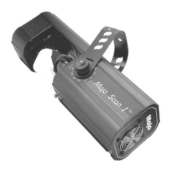
Mojo Scan I
THANK YOU!
Thank you for buying a Geni
product. For best results, please
carefully read and follow the
directions in this product user manual.
TM
Product User Guide
MJC-1XA,MJC-1YA
Advertisement
Table of Contents

Related Manuals for GENI mojo scan I MJC-1XA


Summary of Contents for GENI mojo scan I MJC-1XA
- Page 1 G - Product specification label THANK YOU! H - DMX and function dip switches Thank you for buying a Geni product. For best results, please Note: For simplicity, the back panel of one Mojo product is shown. carefully read and follow the Other product back panels may differ slightly.
- Page 2 2. Turn up the music volume. You can get some of the best quality, best priced products on the market from Geni. So next time, turn to Geni for more great lighting equipment. Always get Product Specifications the best -- with Geni.
- Page 3 Maintenance Mojo Scan I Product Guide Mojo Scan I scanner require almost no maintenance. However, you should: ! Keep the unit clean. Disconnect the mains power supply, then wipe the cover with a damp cloth. Do not immerse in liquid. Wipe lens clean with glass cleaner and a soft cloth.
-
Page 4: Dmx Channel Chart
Description Function Dip Switch Chart Mojo Scan I Small scanner with high output, great effect Instant audio shows and DMX control . OFF Mode ON Mode Mojo Scan I-Sixteen colors and images Single unit show mode Single unit audio show mode The set up, control, and functions of various Mojo Scan I may differ. - Page 5 DMX OUT The lamp may or may not be included, depending on your Geni dealer. In most n e c t i n g e l e c t r i c p o w e r .
- Page 6 Install the Lamp (MJC-IYA) MJC- 1YA scanner use the HTI 152W lamp by Osram only. Four-unit Audio Set Up DMX IN DMX OUT DMX IN DMX OUT DMX IN DMX OUT DMX IN DMX OUT Lamp Installation (MJC-1YA) 1 .Make sure the unit is un-plugged in advance. Loosen the screws on the upper cover with a flat screwdriver, open the upper cover.
Need help?
Do you have a question about the mojo scan I MJC-1XA and is the answer not in the manual?
Questions and answers