
Subscribe to Our Youtube Channel
Related Manuals for Conrad Electronic FS20 SR

Summary of Contents for Conrad Electronic FS20 SR
- Page 1 OPERATING INSTRUCTIONS Version 12/06 Wireless rain sensor „FS20 SR“ Item no. 62 30 18...
- Page 2 Introduction Dear customer, Thank you for purchasing this product. This product meets the requirements of both current European and national guidelines. In order to preserve this condition and ensure the safe operation of the product we kindly ask you to carefully follow these operating instructions! Please read the operating instructions completely and observe the safety and operation notes before using the product! All company names and product names contained herein are trademarks of the...
-
Page 3: Table Of Contents
Function test ......................14 8. The FS20 address system ..................15 9. Programming/operation ................... 20 a) Integrating the ‘FS20 SR’ into the address system ..........20 b) Setting the house code ..................21 c) Setting the addresses ................... 22 d) Manual switching, address transmission ............. -
Page 4: Prescribed Use
15. Declaration of conformity (DOC) ................31 1. Prescribed use The sole purpose of the ‘FS20 SR’ wireless rain sensor is to remotely control the various components of the FS20 wireless control system. It can remotely control these devices on 2 channels (adjustable settings). -
Page 5: Scope Of Delivery
2. Scope of delivery • Wireless rain sensor ‘FS20 SR’ • User manual 3. Explanation of icons The icon with a lightning flash in a triangle is used to alert you to potential personal injury hazards such as electric shock. -
Page 6: Safety Instructions
4. Safety instructions The product’s guarantee becomes invalid, if the product is damaged as a result of the failure to observe these operating instructions! We do not assume any liability for any resulting damages! Nor do we assume liability for damage to property or personal injury caused by improper use or failure to observe the safety instructions. -
Page 7: System Features
5. System features The 2-channel wireless rain sensor ‘FS20 SR’ is a component of the FS20 wireless control system. It can control up to 2 radio receivers in this system with separately adjustable criteria. The high range of up to 100 m (free-field) allows the device to be used to transmit over long distances. -
Page 8: B) Factory Setting
Factory setting The rain sensor ‘FS20 SR’ is immediately ready for use from the factory on channel 1 with the following settings: • On-time of the receiver after rain starts: 1 minute, after which the load is switched off (transmit command) •... -
Page 9: Installation
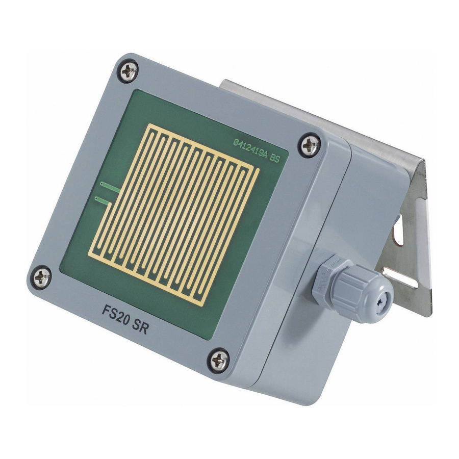
The rain sensor is supplied with an installation bracket that allows for installation on horizontal as well as vertical surfaces. The inscription ‘FS20 SR’ must always be on the underside and the cable bushing must always point to the right. See figure 1. -
Page 10: C) Opening The Casing
c) Opening the casing Use a suitable screwdriver to loosen the four screws in the corners of the top side of the rain sensor. Then carefully remove the cover of the casing. The cables between the sensor and the circuit board are permanently wired. d) Connections and controls TA1 TA2 TA3 TA4... -
Page 11: E) Power Supply
Power supply The rain sensor ‘FS20 SR’ requires a DC or AC voltage of 12-15V. The power consumption is approx. 200mA. Ideally, use a transformer for the power supply that is suitable for outdoor use. A conventional bell transformer or a power supply unit can even be used, however, these may only be connected and operated in dry indoor areas. -
Page 12: F) Connecting The Relay
f) Connecting the relay Warning! Caution! The voltages that are switched by the relay may not exceed 30V~ (AC) or 42V= (DC). The product is not suitable for switching line voltage (230V~/50Hz)! Never switch higher voltages! Not only do you risk destroying the rain sensor, there is also the danger of a fatal electric shock! The maximum load capacity of the relay is 5A. -
Page 13: G) Installation
• Use four screws to mount the bracket at the installation location (see figure 1). • Afterwards, the rain sensor can be mounted to the installation bracket. The inscription ‘FS20 SR’ must always be on the underside and the cable bushing must always point to the right. -
Page 14: Initial Operation
• Set the respective receiver, according to the instructions in its user manual, to the address programming mode. • For channel 1 press button ‘2’ (for channel 2: button ‘4’) on the ‘FS20 SR’. • The LED on the receiver goes out; the switching channel has been programmed. -
Page 15: The Fs20 Address System
The radio transmission is secured by an extensive coding system to allow multiple FS20 components (which also includes the ‘FS20 SR’ rain sensor) to be operated in the same area. The code consists of a ‘house code’ and an ‘address’. The house code serves to differentiate between multiple FS20 systems operating simultaneously. - Page 16 Address group Subaddress Single address Function group address Local master address Global master address This value must be set to ‘44’. This value must not be set to ‘44’. Possible values are: 11, 12, 13, 14, 21, 22, 23, 24, 31, 32, 33, 34, 41, 42, 43 Every receiver can be assigned one address from each of the four address types (single address, function group address, local master address, global master address).
- Page 17 • Global master address Several receivers are assigned to the global master address and are jointly controlled via this address. All the consumer loads can easily be switched off simply by pressing one single button when leaving a house, for example. The figure below illustrates a possible configuration of different FS20 components in a house: House code, e.g.
- Page 18 A different address group has been assigned to each room: • Room A: 11 • Room B: 12 An awning is also allocated to room B. • Room C: 13 • Room D: 14 When you require a large, extended system, it is advisable to select addresses systematically so that you have an overview of the addresses that have already been assigned and so that you can jointly control the programmed receivers simply and logically in groups.
- Page 19 The awning was deliberately not programmed to this address and can therefore only be addressed via its single address (1211). It must be operated separately in this example. The ceiling lamps in all the rooms are also combined in a function group (4411 in the example, address group 44, subaddress 11) and can therefore be jointly controlled.
-
Page 20: Programming/Operation
The ‘FS20 SR’ rain sensor is part of the FS20 wireless control system. For that reason it is of course possible to integrate it into the that code and addressing system, in case you wish to operate various devices of the FS20 wireless control system parallel. -
Page 21: B) Setting The House Code
4 = Button ‘ ’ • The programming mode ends automatically LED goes out once you have entered the eighth digit. The LED goes out. The house code is valid for both channels of the ‘FS20 SR’ rain sensor. -
Page 22: C) Setting The Addresses
c) Setting the addresses The address of a channel (for instance, ‘1431’) consists off a two-digit address group (for instance, ‘14’) and a two-digit subaddress (for instance, ‘31’). The following address combinations (address group/subaddress) are factory set for the two channels of the rain sensor: Channel 1: Buttons ‘... -
Page 23: D) Manual Switching, Address Transmission
Activating/deactivating channels Two plug jumpers are located on the ‘FS20 SR’ rain sensor’s circuit board. They can be used to activate or deactivate each of the channels ( if you only wish to use channel 1, for instance.) ... -
Page 24: F) Setting The Transmit Command
f) Setting the transmit command The ‘transmit command’ is the radio command that is sent to the FS20 receiver when the rain sensor is tripped. This can trigger various reactions from the receiver. Channel 1 Channel 2 • For channel 1 keep button ‘ ’... -
Page 25: G) Setting The On-Time
e) Setting the on-time The ‘on-time’ is the length of time for which the controlled FS20 receiver component remains switched on. The time can be adjusted from 0.25 seconds to 255 minutes (4h 15min). A continuous setting is also available. •... -
Page 26: H) Setting The Interval Time
h) Setting the interval time The ‘interval time’ is the minimum length of time that must pass after the rain sensor has issued its last transmit command and before it is allowed to transmit another transmit command when it detects rain. There are four time-settings available for the interval time: 8, 24, 56 and 120 seconds. -
Page 27: I) Restoring The Rain Sensor's Factory Settings
i) Restoring the rain sensor’s factory settings If you wish to reset the rain sensor to its factory settings (as it was delivered), proceed as follows: • Keep the buttons ‘ ’ and ‘ ’ on the rain Press for sensor simultaneously pressed for 5 seconds. -
Page 28: J) Programming The Receiver's Timer
Programming the receiver’s timer If the receiver that is controlled by the ‘FS20 SR’ rain sensor will also be operated by other transmitters (for example, a hand-held remote control from the FS20 wireless control system) using the internal timer, then the receiver’s internal timer should be programmed as follows: Briefly press its respective button combination (channel 1: buttons ‘... -
Page 29: Information On The Range
10. Information on the range Ranges and interference • The FS20 wireless control system works in the 868MHz range, which is also used by other radio services. Therefore devices that operate on the same or neighbouring frequencies may restrict both its operation and its range. •... -
Page 30: Handling
11. Handling Take note of all the safety instructions in this user manual. Due to the way it is constructed, the rain sensor can be used outdoors provided that its casing and cable bushing are fully and correctly closed. The product must be assembled properly and professionally. Normally the rain sensor is installed only once and remains fixed at the installation location. -
Page 31: Disposal
• Power supply: ........12-15V~/=(AC or DC voltage) • Integrated heating for the sensor surface 14. Declaration of conformity (DOC) We, Conrad Electronic, Klaus-Conrad-Straße 1, D-92240 Hirschau (Germany), hereby de- clare that this product complies with the fundamental requirements and other relevant regulations of directive 1999/5/EG. - Page 32 100% The operating instructions reflect the current technical specifications at recycling time of print.We reserve the right to change the technical or physical paper. specifications. Bleached without © Copyright 2006 by Conrad Electronic SE. Printed in Germany. chlorine.
Need help?
Do you have a question about the FS20 SR and is the answer not in the manual?
Questions and answers