Table of Contents
Advertisement
Advertisement
Table of Contents

Related Manuals for Orban opticodec 7200

Summary of Contents for Orban opticodec 7200
- Page 1 OPTICODEC 7200 / 7400 / PC Remote Handbuch...
- Page 3 OPTICODEC Manual 7200/7400 Software V4.25/2007 REMOTE Software V1.24/2007...
-
Page 4: Table Of Contents
Table of Contents The Codec Technology Update Process Interrupted DSP Software OPTICODEC 7200 and 7400 System Software Hardware Configuration Certification / Labelling Boot Software Description, Introduction and Installation 9 Jumper Settings Important Jumpers on the Main Board OC 7200 Front Panel / Keypad... - Page 5 Table of Contents Dialing Loading System Setup TCP/IP Audio to a Unit Buffer Management Default Configuration Quality of Service Connect Type, TOS, Establishing a Con. w ISDN/IP Dir. Precedence and TOS Values DiffServ, DiffServ Codepoints 36/37 Establishing Connnection Establishing a Con. w. DD Buttons Audio Data Encoder Automatic Connection Start Audio Port (TCP)
- Page 6 Table of Contents System Setup Audio Level Accept Configuration Level Range Algorithm, ISDN Sync Headroom Adjust I/O Levels Samplingrate Interfaces Audio Mode Audio Input External Sync Input Alarm Signals Userdata Backup Settings ISDN Configuration ISDN Protocol Applications 73/75 ISDN Interface Local Numbers Automatic Connection Start SPID Numbers...
-
Page 7: The Codec Technology
The Codec Technology The "ISO-MPEG Audio Layer 2 and Layer 3“ compression procedures developed by the Fraunhofer Institute and the Institut für Rundfunktechnik allow audio signals (even large amounts of data) to be reduced in real time and transferred without any subjective loss of quality. The digitised signals received in this form are compressed (encoded) to save on transmission bandwidth, time and cost. -
Page 8: Opticodec 7200 And 7400
OPTICODEC 7200 and 7400 Certification / Labelling The OPTICODEC units hereafter complies to the following regulations and standards: EN 60950/VDE 0805/IEC 950: Protection Class 1. VBG4, Part 5 paragraph 4: Regulations for the prevention of accidents “Electrical Systems and Materials”. -
Page 9: Description, Introduction And Installation
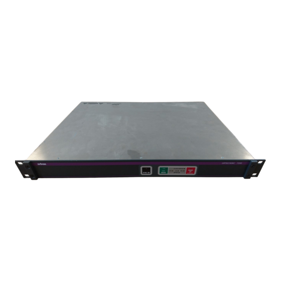
OPTICODEC 7200 and 7400 Description, Introduction and Installation Description The OPTICODEC 7200 and 7400 are fully duplex audio codecs with ISDN and X.21 interfaces as a standard. The OPTICODEC 7400 is also equipped with an Ethernet 100Base-Tx interface for the remote control and distribution of audio data over networks such as Intranet, ATM etc. -
Page 10: Explanation Of Keypad Symbols
OPTICODEC 7200 Front Panel / Keypad Explanation of Keypad Symbols SYNC OK Display of the decoder sync flag. If this LED lightens, the decoder receives correct data from the partner unit. MODUS X.21 Shows an X.21 connection. ISDN Shows an ISDN connection. -
Page 11: Audio Input, Symmetrical
OPTICODEC 7200 and 7400 Rear Panel / Basic Connections (1) Audio input, Level: -4 dBu to.+21 dBu adjustable via symmetrical ‘System Setup’ (+12 dBu preset) Input Imped.: 10 kOhm (switchable over to 600 Ohm, jumper JP 800/801 Connector: XLR jack (female) -
Page 12: Digital In-/Output
OPTICODEC 7200 and 7400 Rear Panel / Basic Connections (4) Digital Input/Output Connector: RCA (female/female) (S/PDlF standard) Center Pin Ring Assignment (5) External adjustable via ‘System Setup’ synchronisation Connector: BNC jack (male/male) Signal level: TTL Center Pin Ring Assignment (6) Serial Synchronous... -
Page 13: Interface (Remote)
OPTICODEC 7200 and 7400 Rear Panel / Basic Connections Assignment Function* * related to OPTICODEC O=output I=input (7) RS232/RS422 to control the OPTICODEC using an external PC (pls. see also chapter ‘PC Connection’, page 18). Serial Asynchronous Interface (Remote) Switch over from RS232 to RS422: Jumper J3 to 1+2 (pls. -
Page 14: Alarm/Control Interface
OPTICODEC 7200 and 7400 Rear Panel / Basic Connections (8) Alarm/Control The switching commands of the OPTICODEC input are Interface transmitted and made available as open collector signals at the partner unit. The inputs and outputs (same as GND connections 13, 25) are electrically isolated via an opto- electronic coupler. -
Page 15: Basic Connections
OPTICODEC 7200 and 7400 Rear Panel / Basic Connections Input Wiring Imax.: 10 mA internal external Output Wiring Imax.: 10 mA Umax.: 25 V internal extrenal external Please note The recommended functions of the inputs and outputs correspond to the way these are assigned by OPTICODEC users. -
Page 16: Basic Connections
OPTICODEC 7200 and 7400 Rear Panel / Basic Connections (9) RS232/RS422 to transmit user data via OPTICODEC. Serial Asynchronous Format: 0 ... 9600 baud (pls. see table) Interface 8 data bits 1 stop bit no parity Table of implemented ancillary data starting from software V4.10... -
Page 17: Standardized Connector
OPTICODEC 7200 and 7400 Rear Panel / Basic Connections (10) Standardized Transmission Rate: 10 Mbit/s Connector Connector: RJ45 to Ethernet Assignment TD+ (11) Standardized Transmission Rate: 2 x B + D channel per S Connectors Connector: RJ45 for S connections... - Page 18 Description The OC PC Remote software is a 32-bit version for Microsoft Windows 98/2k/ME/XP for the remote control of the OPTI- CODEC over the RS232 interface using a PC. It covers the same adjustment parameters as the OPTICODEC itself. Note To avoid any misunderstanding, the ‘OPTICODEC PC Remote’...
-
Page 19: Opticodec Pc Remote
OPTICODEC PC Remote Software Installation Download of the Start the setup program of the current application from the OC Remote Software Internet or from the delivered data medium with a double- click on the setup icon. Follow the installation instructions on the PC screen. -
Page 20: Release Of Additional Features
Release of The menu item 'Enter key codes' is used for release of Additional Features additional features (e.g. the 4SB ADPCM algorithm). The release is dependent on the unit model and its serial num- ber. Each unit receives a unique key code. This function is only active in the standby mode. - Page 21 This function is found on the 'Unit/SoftwareUpdate' pull- down menu. If necessary, please store the device-specific *.BIN file on your local hard drive under Program Files/Orban/Optico- decRemote/Updates. The program automatically recognizes the connected OPTICODEC and which software parts are to be updated.
-
Page 22: Update Process Interrupted
After this interruption the unit cannot be started again, not even by the above described emergency start. It can only be reloaded by ORBAN Europe GmbH in Ludwigsburg/Germany. OPTICODEC... -
Page 23: Jumper Settings
OPTICODEC Jumper Settings Important Attention Jumper Settings Unplug power supply cable before opening the unit! on the Main Board Input Impedance Switching over the input impedance ANALOG INPUT (pls. see page 11) Jumper JP 201/202 1 + 2 set: 600 Ohms 2 + 3 set: 10 kOhms Switch over... -
Page 24: Data Input
Data Input In standby mode select ‘Data Input’ from the main menu or alternatively the 'Data/Edit local directory' pulldown menu.. The telephone directory appears (ISDN/IP Directory). The window and columns widths are variable and can be modified with the mouse. Creating a Open the input mask by clicking onto the function ‘New’. -
Page 25: Isdn Connection
ISDN input fields using the tab key. Once the ISDN numbers have been entered, you can assign a name to the recipient (max. 49 characters). The ISDN/IP address directories of the connected ORBAN Edit Recipient OPTICODEC 7600, OC 7400, CTAXI or PAN-PRO can easily be imported and exported via the 'Data' menu to your PC for more efficient management. - Page 26 Algorithm The ' A lgorithm' menu item is used for presetting the desired data reduction procedure on outgoing calls. By pressing the arrow keys, you can select between Layer 2, Layer 3, G.722, G.711 and 4SB ADPCM (optional). ISDN Sync The 'ISDN Sync' menu item is used to set the desired synchronisation procedure of the partner codec.
- Page 27 OPTICODEC PC Remote Data Input Samplingrate The 'Samplingrate' menu item is used for setting the desired sampling frequency on outgoing calls. You can choose between: 16, 22.05, 24, 32, 44.1, 48 kHz, AUTO (the sampling frequency of the addressing device is used) Audio Mode The ' A udio Mode' menu item is used for setting the desired...
- Page 28 G.722 Connection If you enter a G.722 partner in the ‘Data Input’ menu, please with H.221 observe the following order: or SRT Sync Enter the ISDN number. Enter G.722 in ‘Algorithm’ Determine the Sync modes in ‘ISDN Sync’. Now H=H.221 or S=SRT is displayed in the directory for the selected SYNChronisation procedure.
- Page 29 OPTICODEC PC Remote Data Input Ethernet Connection Should an Ethernet connection be desired, please activate the radio button for Ethernet. Enter the target address and, for easier identification, also enter the name of your connection partner. You may enter both IP address and plain-text names* (* only if a name server also exists).
-
Page 30: Applications
For TRANSMIT and RECEIVE it is to be distinguished whether a broadcast or a multicast transmission is desired. Broadcast A broadcast address must be entered for the unit set to TRANSMIT (for e.g. position #2 in the directory: 255.255.255.255). The unit set to RECEIVE dials the address of the partner unit. -
Page 31: Applications
OPTICODEC PC Remote Data Input / Applications Wide Area Network. Long-distance data traffic networks such as the Internet or connections using ISDN units. Broadcast Describes the data transmission from one unit to all of the other units within the same network. Multicast Describes the data transmission from one unit to all of the others within the same network or another network. -
Page 32: Tip
The local ISDN/IP directory is saved in the 'OpticodecRe- mote‘ program directory as a 'num.dat‘ file. This directory can be easily exported to any number of PCs, hence saving time by copying the same address book directory to all of them. Saving the Unit Use the feature ‘Save directory to disk’... -
Page 33: Loading Isdn/Ip Directory To A Unit
OPTICODEC PC Remote Data Input Loading Click onto ‘Load directory to unit’, locate the desired *.DIR ISDN/IP Directory file and finally activate the ‘Open’ key. to a Unit Select from the directory the desired file format. All 96 entries (connection partners) with their names, ISDN numbers/IP addresses and set audio parameters are now loaded to the unit. -
Page 34: Configuration Of The Connected
Configuration of the Select 'System Setup' from the 'Unit' pulldown menu. The connected OPTICODEC basic configuration menu of the connected OPTICODEC in System Setup differs in appearance depending on the unit type and its equipment. TCP/IP Basics In this menu item the basic settings of the unit within the network are entered. -
Page 35: Tcp/Ip Audio
OPTICODEC PC Remote System Setup Dialing Dialing Attempts This menu item serves for setting the desired dialing attempts. You can select between 1 ... 5 and INFINITE. Dialing Delay This menu items serves for setting the desired time between dialing attempts (between 10 and 360 seconds). Redialing Attempts This menu item serves for setting the desired redialing attempts, if a connection had not been disconnected by... -
Page 36: Quality Of Service
To ensure the most secure transfer possible, the maximum value (bar all the way to the right) should be set; however, this results in a longer delay. If more value is placed on having a shorter delay, then the bar can be moved to the left; however, this has a negative impact on the transmission security. -
Page 37: Audio Data Encoder
OPTICODEC PC Remote System Setup TOS Values TOS Significance TOS Significance 0000 Normal 0010 max. Reliability 1000 min. Delay 0001 min. Monetary Cost 0100 max. Throughtput DiffServ DiffServ uses a new definition of the IPv4 TOS header field and IPv6 traffic class header field. The goal of DiffServ is to subdivide the data traffic into service classes with different priorities, without using the intensive signalling on each router. -
Page 38: Audio Port (Tcp)
Audio Port (TCP) This menu contains the setting for audio transfer over the network with TCP and UDP protocols. For the OPTICODEC, the value 6136 should always be entered. TCP/IP Remote Control Unit Name For easier identification of devices on the network, the name of your OPTICODEC must be entered here without name length restrictions. -
Page 39: Autodetect
The ‘AUTO’ mode is not available for ‘Audio Input’ and ‘Userdata’. Descriptions starting page 26. Statements about the audio compatibility (via ISDN) with external codecs can be found on the supplied data carrier or on the Internet at: www.orban-europe.eu. OPTICODEC... -
Page 40: Redialing Attempts
Dialing Dialing Attempts This menu item serves for setting the desired dialing attempts. You can select between 1 and 5. Dialing Delay This menu item serves for setting the desired time between dialing attempts (between 10 and 60 seconds). Redialing Attempts This menu item serves for setting the desired redialing attempts, if a connection had not been disconnected by the calling OPTICODEC. -
Page 41: Isdn Configuration
OPTICODEC PC Remote System Setup ISDN Configuration ISDN Protocol The OPTICODEC has two ISDN D-channel protocols: EURO (DSS1) and NATIONAL 1 (North America). For use in the USA, the OPTICODEC is equipped with 'IMD4‘ type ISDN modules. This is necessary if additional U interfaces are required for North America. -
Page 42: Isdn Interface
(using a ISDN module type 'IMD4'). Number Prefix for These settings concern incoming calls for OPTICODEC 7200 incoming calls and 7400. If the ' A dd PBX Prefix‘ option is set to 'YES‘, the number from the PBX Prefix (see 'Dialling‘, page 40) is in- serted before the number for incoming calls. -
Page 43: Local Numbers
OPTICODEC PC Remote System Setup Local Numbers The ISDN numbers entered here are sent when the con- nection has been established. Under certain conditions (e.g. private branch exchange (PBX)* type), the individual ISDN number must be entered. without PBX* on PBX* can remain vacant can remain vacant 1 x unit only... -
Page 44: I/O Levels
I/O Levels This menu item serves for setting the analog Input and Output levels for the left and right channels. Ex-factory the setting is +12 dBu, the headroom is 0 dB. This means: input level = output level = 12 dBu. With a mouse click on the ‘up’... -
Page 45: Level Range, Headroom
OPTICODEC PC Remote System Setup Level Range This menu item allows the adjustment at the level range: 50 or 80 dB. Headroom This menu item serves for setting the desired headroom. You can select between 0 and 20 dB in 1 dB steps. Ex- factory the setting is 0 dB. -
Page 46: Backup Settings
Backup Settings In the 'Backup Settings' mode you can allocate an entry of the ISDN directory to each input port of the Alarm/Control Interface. To do this, you must select the requested input port. Press the ‘Cfg’ (Configuration) key to allocate an ISDN number to this input port. - Page 47 OPTICODEC PC Remote System Setup When the unit is in the X.21 mode and the X.21 clock fails, the unit returns to the main menu and the ISDN connection is then established. As soon as the X.21 clock is active again, the ISDN connection is disconnected and the unit returns to the X.21 mode.
-
Page 48: Loading System Setup
Saving the Units Similarly to that of the ISDN/IP directory (pls see page System Setup to Your 30), there is alternatively the possibility to save the system Harddisk configuration of the OPTICODEC onto your PC harddisk for archive purposes, for example. Use the ‘Save System Setup to Disk’... -
Page 49: Connect
OPTICODEC PC Remote Connect Connect The respective connection can be established quickly and easily. A pre-requisite for the connection establishment is the correct initializing of the OC Remote software with the connected OPTICODEC. This is confirmed with the ‘Standby’ status message in the program screen. Establishing a Select the ‘Connect’... - Page 50 Establishing Connection Select your ISDN connection partner from the list using the mouse. The selected connection partner is marked and displayed inverted. Press ‘Connect’ to confirm. The connection is now being established. After successful synchronization, your OC Remote program displays the message ‘Connected’ and goes to the online menu.
-
Page 51: Automatic Connection Start
OPTICODEC PC Remote Connect Note The connection parameters for Layer 2 and Layer 3 are determined as follows: Only entry of the first ISDN number. 64 kbps, 48 kHz, Mono, User Data 1200 baud. For the entry of two ISDN numbers: 128 kbps, 48 kHz, Joint Stereo, User Data 1200 baud. -
Page 52: Currency Icon
In addition, together with the send (Tx) and receive con- figuration (Rx), the IP address / ISDN number (according to the connection type) of your codec partner are shown on the display. $ Currency Icon After the establishment of an ISDN connection, in addition to the connection duration, the currency icon ($) is also activated. - Page 53 OPTICODEC PC Remote Connect Establishing a From the Directory, select an entry with ‘X.21’ as the digit Connection with X.21 of the ISDN number. Establishing a From the Directory, select an entry without an ISDN num- Connection with ber. The connection is established via the Directory, 'Quick Codec Loop Dial' or 'Direct Dial Buttons'.
-
Page 54: Opticodec 7400
OPTICODEC 7400 Front Panel / Keypad The OPTICODEC 7400 is a fully duplex ISDN audio codec with an Ethernet interface for the remote control of the unit and the possibility to distribute audio over networks such as Intranet, ATM etc. Configuration and operation of the unit takes place using the numeric keypad and/or the control software OC Remote and NETControl. - Page 55 OPTICODEC 7400 Front Panel / Keypad G.711 activates the G.711 algorithm Copy copies a telephone number cursor jumps to the left G.722 activates G.722 algorithm PgUp cursor jumps upwards to next page cursors jumps to the right Layer 2 activates Layer 2 algorithm PgDn cursor jumps downwards to next page Layer 3...
-
Page 56: Data Input
OPTICODEC 7400 Data Input Data Input After switching the unit on and after a short initializing sequence the 3 pages of the basic configuration menu of the OPTICODEC 7400 appears (see also „Status Messages“, page 82). After selecting the menu ‘Data Input’ and confirming with the ‘Enter’... -
Page 57: Isdn Connection
OPTICODEC 7400 Data Input ISDN Connection The option ‘ISDN/X.21’ must be selected in the line for connection type if an ISDN connection is required. ISDN Number Depending on the number of ISDN modules, input fields between ISDN#1 and ISDN#4 are displayed. Entries are made using the numerical keypad. -
Page 58: Shortname
OPTICODEC 7400 Data Input Audio Data Encoder In this menu you can determine all audio parameters for the planned connection. This menu leads you through settings for Algorithm (Layer II, Layer III, G.711, G.722 and optionally 4SB ADPCM), Bitrate and up to User Data. Do not forget to correctly define the audio input: AES/EBU for digital units in professional format, S/PDIF for digital units in consumer format, ANALOG for analog units. -
Page 59: Ip Connection
OPTICODEC 7400 Data Input IP Connection Should an Ethernet connection be selected, you can then set the desired IP connection. The following connenction modes are possible: Point-to-Point A bi-directional connection between two units. TCP is utilised as the protocol, possible transmission errors are corrected to a certain degree by this protocol. -
Page 60: Multicast
OPTICODEC 7400 Data Input Here you enter the IP addresses for the desired connec- tion. The addresses to be entered are dependent on the desired transmission protocol: POINT-TO-POINT mode: The local IP address of the partner unit is to be entered. For TRANSMIT and RECEIVE it is to be distinguished whether a broadcast or a multicast transmission is desired. - Page 61 OPTICODEC 7400 System Setup System Setup By pressing the UP/DOWN buttons, select System Setup from the main menu and confirm with the ‘Enter’ button. Accept This sets up the call accept mode of the OPTICODEC. Configuration First you can set the accept mode Audio Data Encoder for the unit and transmission more or less specific and perma- nently.
- Page 62 OPTICODEC 7400 System Setup The possible Sync modes are: MusicTAXI (MusicTAXI Sync for 1 to 4 B-channels) PRIMA (CCS Sync for 2 B-channels) ZEPHYR (Telos Sync for 2 B-channels) AETA (for 4SB ADPCM algorithm; optional) NO SYNC when using 1 B-channel NO SYNC (INV) when using 1 B-channel AUTO - Automatic Audio Codec Detection The release of the AETA sync and the 4SB ADPCM al-...
- Page 63 OPTICODEC 7400 System Setup ISDN Configuration ISDN Protocol The OPTICODEC has several ISDN D-channel protocols. Please make sure that you have selected the correct pro- tocol. Decisive is the ISDN protocol of your connection, not the one of the partner unit! Alter the settings by pressing the 'Enter' key.
- Page 64 OPTICODEC 7400 System Setup SPID Numbers The SPID numbers entered here are also sent when a connection is being established. This is necessary only when operating on USA or Canadian networks. The identification number input and allocation takes places as described in “Local Numbers”. Dialing Dialing Attempts Here the number of dialing attempts between 1 and 5 can...
- Page 65 OPTICODEC 7400 System Setup Incoming Calls The menu item 'Incoming Calls' defines the behavior of the OPTICODEC during operation on a S connection together with other units. Accept First set ' A ccept Telephone Calls' to: Telephone Calls ALWAYS every telephone call is accepted NEVER all telephone calls are rejected manual confirmation of each call is requested...
- Page 66 OPTICODEC 7400 System Setup TCP/IP Configuration TCP (Transmission Control Protocol) is one of the most important protocol specifications of the network protocols. TCP is a connection-oriented protocol and provides a re- liable, byte stream service. This menu item determines the basic settings of the OP- TICODEC for operation in the network.
- Page 67 OPTICODEC 7400 System Setup Should an address be allocated twice, the following error message appears: abc.def.ghi.jkl is the own IP address which is currently set and xx is a counter which displays the seconds to go before the automatic restart. With ‘Enter’, the menu to enter the local IP address appears.
- Page 68 OPTICODEC 7400 System Setup Default Gateway The data exchange between the different cross points of the network is transparent for the user. The IP-stack recognizes whether a data packet is scheduled for another network and will then address the default gateway. This corresponds for e.g.
- Page 69 OPTICODEC 7400 System Setup Port An important part of the TCP/IP model are the port numbers, also known as socket numbers. With these ports, it is advised which service is desired (pls. s. ‘Port’ on page 38). The value 6137 should always be entered for the OPTICODEC.
- Page 70 OPTICODEC 7400 System Setup To achieve the highest possible transmission reliability with a low delay, it should be ensured that no further units are simultaneous transmitting data within the network. Port Here the port number for audio transmission is entered. Always enter the value 6136 for the OPTICODEC.
- Page 71 OPTICODEC 7400 System Setup Type QoS (when the router has been configured accordingly) actively regulates traffic in the net and utilises the available bandwidth both intelligently and effectively on the basis of data priority and bandwidth reservation. TOS (Type of Service) or DiffServ (Differentiated Service Architecture) are the key mechanisms of QoS and are responsible for the assessment of packet priority.
-
Page 72: Headroom
OPTICODEC 7400 System Setup Audio Levels Level Range This menu item allows the adjustment of the level range: 50 or 80 dB. Headroom This menu item serves for setting the desired headroom. You can select between 0 and 20 dB steps. Ex-factory the setting is 0 dB. -
Page 73: Alarm Signals
OPTICODEC 7400 System Setup Interfaces External Sync Input The OPTICODEC has a sample rate converter at the audio input and output. For the external SYNChronization of the digital output you can select between: DISABLED Word clock is generated from the transmission clock DIGITAL IN Word clock is generated from the AES or S/PDIF input signal... - Page 74 OPTICODEC 7400 System Setup This number corresponds directly in all parameters with the entry in the ISDN directory. After entering the number, you have to confirm your setting by pressing the ‘Enter’ button. If you enter only one digit for the number, the OP- TICODEC will automatically add a 0 before the digit.
- Page 75 OPTICODEC 7400 System Setup Applications by Using Backup Settings: Satellite/ISDN Redundcy Assuming the satellite receiver can indicate an opto- decoupled error message, you can connect this information to the alarm/control interface. If the error message is ON, the OPTICODEC will automatically establish an ISDN connection to the relevant entry number.
- Page 76 OPTICODEC 7400 System Setup Under entry number 96, enter an “X”, an ISDN number or an IP address and AUTOCON as the name (SHORTNAME). Also set up the desired configuration under AUDIO DATA ENCODER. Confirm your entry with EXIT using the ‘Enter’ button.
-
Page 77: Reset Configuration
OPTICODEC 7400 System Setup T1: Time, how long the X.21 mode must fail before the ISDN connection is established. T2: Length of time for an ISDN connection to be established. T3: Time, how long the X.21 clock must again be active before the ISDN connection is again disconnected. - Page 78 OPTICODEC 7400 Connect Connect The respective connection can be established quickly and easily. Select ‘Connect’ from the main menu and press ‘En- ter’ to confirm. The directory for IP addresses and ISDN numbers with 96 entries appears. For connection establishment you can decide between a connection via the ISDN/IP directory, quick dialing or manual input with the numeric keypad.
- Page 79 OPTICODEC 7400 Connect After successful synchronization, your OPTICODEC displays the message ‘ISDN OK’ and goes to the online menu. If the connection is rejected, the OPTICODEC displays ERR(OR) and the reason for rejection. Check the error reports using the error codes listed in the appendix, starting page 83.
-
Page 80: Connection Monitoring
OPTICODEC 7400 Connect Establishing a First you have to determine the transmission mode. Via Connection Using the keypad you select between G.711 (3.1 kHz, telephone), G.722 Direct Dial Keys (7kHz, H.221/SRT), Layer 2 and Layer 3. The input menu asks for the ISDN number to be entered using the numeric keypad as usual. - Page 81 OPTICODEC 7400 Connect Sync Icon The Sync symbol in the Rx path confirms that the decoder of your connection partner receives the correct data. The Sync symbol only appears for connections between OP- TICODECs 7200/7400 and only for Point-to-Point and ISDN connections in Layer 2 and Layer 3.
-
Page 82: Status Messages
OPTICODEC Status Messages / Number Codes in Standby Mode In the online menus of the OC Remote software and OPTI- CODEC 7400 the following messages may be displayed: Status Messages Possible Cause No X.21 clock was determined. • NO X.21 CLOCK •... - Page 83 ISDN Error Messages Error message Possible causes Checkpoint/ workaround • ISDN NOT RESPONDING The OPTICODEC could not • Check the ISDN connection and establish a communication to the cable, and try the ISDN connection: again. • ISDN cable not connected. •...
- Page 84 ISDN Error Messages Error message Possible causes Checkpoint/ workaround • NO CHANNEL The cause is attributable • Try again later. AVAILABLE to the ISDN, i.e. it is not • NETWORK OUT OF possible for the ISDN ORDER network to establish the •...
- Page 85 ISDN Error Messages Error message Possible causes Checkpoint/ workaround • INVALID CALL These error messages are • Check the set ISDN REFERENCE VALUE generally caused by an in- protocol and try • IDENTIFIED CHANNEL correctly set ISDN protocol. again. DOES NOT EXIST •...
- Page 86 Brief Lexicon Ethernet Error Messages Standardised Audio Compression Procedures (Algorithms) • G.711 Standardised audio compression procedure for speech transmissions over ISDN. This algorithm requires 64 kbps bandwidth and supplies audio quality of up to 3.1 kHz ("telephone“). • G.722 This algorithm requires a data rate of 64 kbps and supplies audio quality of up to 7 kHz („radio quality“).
- Page 87 Technical Specifications Mechanic Size: 19“, (2U 7400 and 1U 7200), depth: 380 mm, temper.: -10 ° C ... +45 ° C, no fan necessary, relative humidity: 30 ... 90 %, Line voltage: 100 ... 240 V AC, 50/60 Hz, 0.375 ... 0.20 A, max.
- Page 88 OC7400/X.21 without 10Base-T and S interfaces Delivery OPTICODEC 7200 unit (incl. power supply cable, length: 2m) Scope ISDN cable (RJ45 type CAT5), length:2 m)** PC connection cable (type: KB003, serial 9pole cable) user manual+ CD-ROM with OC PC Remote software =only for units with 10Base-T interface;...
Need help?
Do you have a question about the opticodec 7200 and is the answer not in the manual?
Questions and answers