
Related Manuals for Danfoss air


Summary of Contents for Danfoss air
- Page 1 MAKING MODERN LIVING POSSIBLE Danfoss Air Installation manual for Danfoss air units and duct systems DANFOSS HEATING SOLUTIONS...
-
Page 2: Table Of Contents
Unit installation 2.1 Installation of Air unit and condensate duct ......4 2.2 Electrical installation . -
Page 3: The Danfoss Air System
• A quick guide (located behind wall plate on consists of: the wireless remote) • Wireless remote control - called Air Dial below If you have ordered the complete Danfoss Air (4 AAA batteries included) Solution, there will be a complete packing list that • A communication module - henceforth the also follows the duct system. Please check that CCM module packing list matches supplied components. -
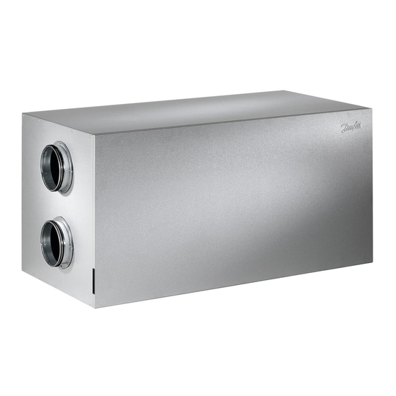
Page 4: Unit Installation
Please note! A siphon must always be fitted Attic units a and a top view on the unit. The siphon is a Danfoss accessory which must be ordered separately. Power supply and Condensate drain connection of CCM module Ø19 (smooth) Hose clamp Supply air... - Page 5 Instructions Unit installation Wall Air units instructions w & w Place the wall mounting bracket on wall in desired position, 75 mm from the bottom of the bracket to the top of the unit, mark up- and drill holes. Use screws suitable for the wall surface (screws are not included).
- Page 6 Instructions Unit installation Ø19 mm plastic pipe Hose clamp 3/4” pipe 3/4” coupling VIEWA402...
-
Page 7: Electrical Installation
If an ethernet connection is already available in Important the vicinity of the Air unit, place the communi- If the communication module is mounted in cation module close to this, to allow for future different floor than wireless remote, please check connection to PC. -
Page 8: Wireless Connection
Installation of Air Dial - optimum placement 2. Select the Link Test menu. When mounting the Air Dial, please place according 3. The Air Dial then tells you if the conditions are to following guidelines to ensure best possible satisfactory or not. -
Page 9: Setting Up Main Air Volume
4. Find the required flow on the system diagram uring points and use the same procedure to set (blue sticker) with the corresponding differential up the supply air. All that remains is to set up pressure value. This is the pressure the measur- the room air volumes. -
Page 10: Technical Data
Weight of unit: 31 kg for supply air Optional supply air connector located on bottom of w1. To of the normal supply air connector. Then fit the supply air use, remove top supply air connector by loosening screws, connector on bottom. -
Page 11: Dimensions - W2 Unit
Technical data 3.2 Dimensions - w unit Top view Top view Ø160 Exhaust Ø160 Extract Ø160 Ø160 Supply Outdoor air Isometric drawing Front view (frontpanel removed) Filter reset button Filter, supply air Filter, extract air Differential pressure for extract air... -
Page 12: Dimensions - A2 Unit
(on back) Exhaust air Exhaust Weight of unit: 67 kg 3.5 Details - front panel removed Front view (without front panel) Filter, exhaust air Filter reset button Differential pressure Differential pressure for extract air for supply air Filter, supply air... -
Page 13: Technical Data - W1 Unit
(A) Unit / Gerät / Anlæg til rum: 55 (4) Exhaust / Abluft / Udsugning @ 180 m3/h Danfoss Air w (5) Supply / Zuluft / Indblæsning @ 180 m3/h (6) Hard room / Harter raum / hårdt rum @ 180 m3/h 3.7 Technical data - w... -
Page 14: Technical Data - A2 Unit
(6) L (4) Exhaust / Abluft / Udsugning @ 260 m3/h Danfoss Air a (5) Supply / Zuluft / Indblæsning @ 260 m3/h (6) Hard room / Harter raum / hårdt rum @ 260 m3/h 3.9 Technical data - a unit Flow properties / Strömungsverhältnisse / Luftdata... -
Page 15: Menu
Air Dial asks for the required basic step from the Air Dial. The Air Dial is now ready in during the registration procedure. start-up mode. -
Page 16: Valve Installation
Guidelines for valve locations: Air diffusion Extraction Try to avoid placing air diffusion valves above Designed to remove moist ”contaminated” air places where people may be located for long pe- and should therefore be positioned as close as riods such as above sofas, beds, dining table, etc. -
Page 17: Installing The Valves
Instructions Valve installation 5.3 Installing the valves Fix the bayonet socket that will hold the valve to the insulation section and installing a duct sec- the ceiling. If it is a gypsum ceiling, we recom- tion along a suitable length of the bayonet socket mend putting a wooden plate on the back for (VGU or VGM). -
Page 18: Installing The Duct System
Instructions Installing the duct system 6.1 In general To get the best out of the system and to achieve Example optimum operational efficiency, you should duct installations… install the duct system as compactly as the build- ing construction will allow. In practice, this means that you should keep your duct sections as short as possible and use as few bends as possible in order to achieve the lowest possible loss of pres-... -
Page 19: Connecting The Duct System
It is recommended to use an insulated flex pipe Ø 125 type THISOL. Ø 125 Ø 100 Example Mount hose clamps around the outer layer of plastic in order to ensure air tightness. Ø 125 Ø 100 TCPU Ø 125 RCFU Ø 100 Ø 125 RCFU Ø... -
Page 20: Insulating The Duct System
30 mm of insulation to protect against condensation. Where there is a pre- heating surface or a geothermal surface, the insulation of the fresh air intake should be at least 100 mm. • 50 mm of insulation will be adequate for sound dampers, as they already have 50 mm of insulation. -
Page 21: Sound Damping Of The Duct System
Instructions Installing the duct system 6.5 Sound damping Sound damping the duct system is a very impor- of the duct tant element in achieving the general feeling that Unit system you have the perfect indoor climate. The noise in a ventilation system comes primarily from the unit’s ventilators. -
Page 22: Adjusting The Valves
Instructions Installing the duct system 6.7 Adjusting the Supply air Extract air valves Start by fully closing the valve (not too tight!). Start by setting the valve to position 0, which in Then open the valve the number of times indi- practice means opening the central cone so that cated in the diagram. -
Page 23: Setting Up
Setting up the system 7.1 Setting up the Once the system has been fully installed, we rec- system ommend having it set up professionally in order to achieve optimum operation. Contact Danfoss Ventilation A/S for information on your nearest approved installer. VIEWA402... - Page 24 This has always been our legacy, and the new delivering solutions used in all aspects of heating Danfoss products are sold, serviced and valued Danfoss Air system is set to carry on this proud and cooling, such as valves, thermostats, pumps around the world. Danfoss products also play tradition.
Need help?
Do you have a question about the air and is the answer not in the manual?
Questions and answers