Table of Contents
Advertisement
Quick Links
Advertisement
Table of Contents

Related Manuals for Thermomax SM DUE


Summary of Contents for Thermomax SM DUE
- Page 1 THERMOMAX SM DUE TWO CHANNEL DATALOGGER AND ALARM ENGLISH www.Thermomax-Group.com...
-
Page 2: Table Of Contents
..............3.7.1 Transferring Data Using the Masterlink Software ..3.7.2 Transferring Data to the Masterlink Hardware ... 3.7.3 Printing Data to the Thermomax Serial Printer .... 3.8 - DATA TRANSFER - PANELMOUNT UNITS ONLY ......23 SECTION 4 - FAULT FINDING .................…. -
Page 3: Section 1 Introduction
SECTION 1 INTRODUCTION The SM DUE microprocessor-based datalogger uses the novel approach of a paperless logging and filing system, which allows the data of any day in its history to be read and examined with a few key presses. The large graphics LCD display communicates the information to the user with clarity, making programming and setting up friendly and uncomplicated, without compromising its sophistication and digital accuracy. -
Page 4: Section 2 Installation
SECTION 2 INSTALLATION Note: This installation procedure is for guidance only, and its suitability should be verified by the installer. SAFETY PRECAUTIONS Before attempting to install and operate the unit, read this instruction manual carefully. Installation and any maintenance required should only be carried out by suitably qualified personnel. -
Page 5: Sm Due Unit
Position the moulding and slot in the lug over the screw. 2.2.3 Level the SM DUE moulding and, if using rear entry, mark the entry holes in the panel behind the appropriate knock-out entries, as well as the two lower mounting holes. -
Page 6: Alarm Relay
ALARM RELAY NOTE: The alarm relay is a 3 contact changeover arrangement that is isolated (volt-free). This relay is normally energised, and switches off when the alarm is triggered, or in the case of power failure. It may be used to trigger an external bell, warning lamp, or digital communicator (telephone dialler). -
Page 7: Section 3 - Operation
SECTION 3 SM DUE OPERATION In order to fully understand the operation of the SM DUE, this section should be read carefully. 3.1 DESCRIPTION MIN -6.0 MAX -5.5 °C SM DUE GRAPHICS LCD DISPLAY Displays all the information. The contrast is adjustable to suit the user. - Page 8 SET KEYS keys are used to set the value of any selected parameter, by increasing and decreasing the value respectively. In most of the functions, described later in the manual, the keys have an auto-repeat facility: press and hold the key in order to advance quickly. Note: The keys are the only keys which can alter the value of a selected parameter.
-
Page 9: Main Screens
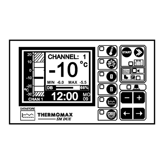
MAIN SCREENS 3.2.1 MAIN SCREEN 1: CHANNEL TEMPERATURE DISPLAY SM DUE MAIN SCREEN function selector. Two channel digital temperature display, viewed in either °C or °F. High and Low Alarm Limits for each channel plus date of last alarm. Maximum and minimum daily temperatures for each channel. -
Page 10: Main Screen 2: Current Day Plot Screen
Alarm Log: Alarm indication to reveal the incidence of an alarm, the time it occurred and its duration. Unique electronic serial number of SM DUE. ‘Other Channel’ Range: Display of max. and min. temperatures recorded. This area of the display shows any occurrence of a cold room door opening. -
Page 11: Set Screens
SET SCREENS 3.3.1 SET SCREEN 1: CLOCK/CALENDAR SM DUE SET SCREEN function selector The datalogging system uses the calendar to file the logged data. Selection indicator The highlighted parameter is adjusted by pressing the key. . (The selections are: ‘year’, ‘month’, ‘day’, ‘↑’, ‘hour’ and ‘minutes’.) The ‘↑’... -
Page 12: Set Screen 2: System Pre-Sets 1
SET SCREEN function selector Pressing this key a second time reveals Set Screen 2. Alarm Mute To mute the SM DUE’s internal audible alarm, press the key when the MUTE window is selected. When the alarm system is reset, either manually or by the temperatures dropping within pre-set limits, the alarm mute will be cancelled automatically. - Page 13 This allows the user to ensure both are functional. Door Switch Selection. The SM DUE provides the option to connect a door switch for monitoring purposes, the status of the door is displayed and logged in graphical form (see section 3.2.2). This option may be enabled or disabled by pressing the key respectively.
-
Page 14: Set Screen 3: System Pre-Sets 2
3.3.3 SET SCREEN 3: SYSTEM PRESETS 2 SM DUE SET SCREEN function selector Pressing this key a third time reveals Set Screen 3. Alarm Mute Period for Channel 1 (from 0 to 95 minutes). If any key is pressed during an Alarm situation for this channel, the buzzer will be muted (silenced) for this period. -
Page 15: System Diagnostics
SYSTEM DIAGNOSTICS 3.4.1 DATABANK DIAGNOSTICS SCREEN SM DUE This is the unique electronic signature of the SM DUE. The DATABANK window shows the capacity of the internal databank. There are two SM DUE options available: (a) Recording frequency 5 minutes – Databank capacity 570 days (approx. -
Page 16: Channel Diagnostics Screen
The CALIB DATA window shows calibration values, for factory use only, and the current temperature reading. The LAST CALIB window shows the date when the SM DUE was calibrated, (in this case 5 JAN 99). The AL. HIGH window shows the date when the last high alarm condition occurred for this channel. -
Page 17: Calibration Trimming Screen
3.4.3 CALIBRATION TRIMMING SCREEN Calibration trimming allows qualified personnel to adjust the SM DUE’s calibration by ± 2°C. Note: A known reference temperature should be used. CALIBRATION PLEASE REFER TO MANUAL SM DUE To enter the CALIBRATION TRIMMING Screen, press and hold the for 5 seconds. -
Page 18: Channel Screens
MIN -6.0 MAX -5.5 °C DOOR OPEN SM DUE CHANNEL 1 function selector: displays the information for channel 1. CHANNEL 2 function selector: displays the information for channel 2. Clock display: 24-hour format with day of week abbreviation. Temperature bargraph: High and low alarm limits are shown as shaded areas. -
Page 19: Channel Set Screens
3.5.2 CHANNEL SET SCREENS SM DUE Channel 1 function selector Channel 2 function selector Pressing either of these keys a second time will display the “Channel Set Screen” for the appropriate channel. Bargraph Display Scale By pressing the key, the bargraph display scale may be adjusted to show the temperature range best suited to the particular installation. -
Page 20: Plot History
PLOT HISTORY 3.6.1 DATA LOG OF PREVIOUS DAYS SM DUE Plot History function selector When this key is pressed, the directory of the contents of the internal databank is displayed, as above. The highlighted months on this screen are the months for which the databank contains data. -
Page 21: Data Transfer
DATA TRANSFER The SM DUE is supplied with an internal reusable 1 ½ year databank. The contents of this databank may be transferred directly to the PC using the MASTERLINK Software or, alternatively, the MASTERLINK Hardware may be used as an intermediate storage device to transfer data to a PC at a remote location. - Page 22 Masterlink Hardware – from 1 day up to the total number of days stored in the internal databank of the Thermomax unit. In this example, there are 61 days of data stored in the Databank.
-
Page 23: Printing Data To The Thermomax Serial Printer
The user can now choose any number of days, (starting from the current day), to print directly to the Thermomax serial Printer – from 1 day up to the total number of days stored in the internal databank of the Thermomax unit. -
Page 24: Data Transfer - Panelmount Units Only
• Direct connection to PC • Direct connection to Masterlink Hardware • Direct connection to Thermomax Serial Printer The unit is despatched from Thermomax in this mode. Masterlink Hardware Unit - C0321 Thermomax Serial Printer - A6747 Mode 2 This mode is used to network up to 32 units to one PC, (see illustration below). - Page 25 MODE 1 – STANDARD MODE (DISABLING NETWORK MODE) If the network is enabled and the user tries to download data to the Masterlink Hardware or print directly to the Thermomax Serial Printer, the following screen will appear. DATA TRANSFER FUNCTION...
- Page 26 The following screen will appear: SM DUE To disable the network press the key. (When the key is pressed, the SM Due will switch off and back on again). If you do not wish to disable the network, press the key. .
- Page 27 MODE 2 – NETWORK MODE (SELECTING NETWORK MODE) To select the network mode, press the key twice to reveal the following screen: SM DUE Select the window by using the key and press the key to show the following screen:...
-
Page 28: Section 4 Fault Finding
SM DUE To enable the network press the key. (When the key is pressed, the SM Due will switch off and back on again). If you do not wish to enable the network, press the key. . SECTION 4 FAULT FINDING Problem: Nothing happens when the unit is powered-up. -
Page 29: Section5 Specifications
May be used for low or mains voltage MECHANICAL: Dimensions: width: 165mm height: 160mm depth: 75mm weight: SM DUE Unit: 0.96Kg Sensor: (each) 0.13Kg Box Material: Plastic Front Panel: Reverse printed Display: Large LCD supertwist graphics SENSORS: Type: PT 100 Platinum Film... -
Page 30: Keypad Lock
5 seconds. To unlock, press the key and hold for 5 seconds. When the keypad is locked, the SM DUE enters into a security mode, which renders the unit ‘tamper-proof’. There are three functions for which the set keys ( ) will operate when the keypad is locked. -
Page 31: Sm Due Panelmount
SM DUE PANELMOUNT DIMENSIONAL DETAILS... - Page 32 WIRING DIAGRAM NOTE: For SM DUE applications: CH1 = CH1 CH2 = CH2 Alarm Relay max 5A THERMOMAX PANEL-MOUNT Transformer 12V 220 / 240 VAC 50Hz...
Need help?
Do you have a question about the SM DUE and is the answer not in the manual?
Questions and answers