Pioneer PD-117 Service Manual
Hide thumbs
Also See for PD-117:
- Catalog (10 pages) ,
- Operating instructions manual (38 pages) ,
- Service manual (28 pages)
Table of Contents
Advertisement
Quick Links
COMPACT DISC PLAYER
PD-217
PD-117
THIS MANUAL IS APPLICABLE TO THE FOLLOWING MODEL(S) AND TYPE(S).
Type
Model
RFXJ
AC110-127V/ 220-240V
PD-217
PD-117
RFXJ
AC110-127V/ 220-240V
For details, refer to "Important symbols for good services" .
PIONEER CORPORATION
PIONEER ELECTRONICS (USA) INC. P.O. Box 1760, Long Beach, CA 90801-1760, U.S.A.
PIONEER EUROPE NV Haven 1087, Keetberglaan 1, 9120 Melsele, Belgium
PIONEER ELECTRONICS ASIACENTRE PTE. LTD. 253 Alexandra Road, #04-01, Singapore 159936
PIONEER CORPORATION 2004
Power Requirement
4-1, Meguro 1-chome, Meguro-ku, Tokyo 153-8654, Japan
PD-217
The voltage can be converted by the following method.
With the voltage selector
With the voltage selector
ORDER NO.
RRV2904
T – ZZR MAR. 2004 Printed in Japan
Advertisement
Table of Contents

Related Manuals for Pioneer PD-117


Summary of Contents for Pioneer PD-117
- Page 1 PIONEER CORPORATION 4-1, Meguro 1-chome, Meguro-ku, Tokyo 153-8654, Japan PIONEER ELECTRONICS (USA) INC. P.O. Box 1760, Long Beach, CA 90801-1760, U.S.A. PIONEER EUROPE NV Haven 1087, Keetberglaan 1, 9120 Melsele, Belgium PIONEER ELECTRONICS ASIACENTRE PTE. LTD. 253 Alexandra Road, #04-01, Singapore 159936 PIONEER CORPORATION 2004 T –...
-
Page 2: Safety Information
SAFETY INFORMATION This service manual is intended for qualified service technicians ; it is not meant for the casual do- it-yourselfer. Qualified technicians have the necessary test equipment and tools, and have been trained to properly and safely repair complex products such as those covered by this manual. Improperly performed repairs can adversely affect the safety and reliability of the product and may void the warranty. - Page 3 [ Important symbols for good services ] In this manual, the symbols shown-below indicate that adjustments, settings or cleaning should be made securely. When you find the procedures bearing any of the symbols, be sure to fulfill them: 1. Product safety You should conform to the regulations governing the product (safety, radio and noise, and other regulations), and should keep the safety during servicing by following the safety instructions described in this manual.
-
Page 4: Table Of Contents
CONTENTS SAFETY INFORMATION ............................2 1. SPECIFICATIONS ..............................5 2. EXPLODED VIEWS AND PARTS LIST ....................... 6 2.1 PACKING SECTION ..........................6 2.2 EXTERIOR (1/2)SECTION ..........................8 2.3 EXTERIOR (2/2)SECTION ........................................9 2.4 SINGLE MECHANISM SECTION ........................10 3. -
Page 5: Specifications
Weight ................... 3.1 kg External dimensions PD-217 ........420(W) X 101(H) X 267(D) mm PD-117 ........420(W) X 101(H) X 263(D) mm 2. Audio section Frequency response ........... 2 Hz - 20 kHz S/N ratio ............98 dB or more (EIAJ) Dynamic range .......... -
Page 6: Exploded Views And Parts List
For the applying amount of lubricants or glue, follow the instructions in this manual. (In the case of no amount instructions, apply as you think it appropriate.) 2.1 PACKING PD-117 Only FRONT PD-217... - Page 7 Battery Cover See Contrast table (2) Dry Cell Batteries(AA/R6P) VEM1031 Control Cable (L=1.0m) See Contrast table (2) (2) CONTRAST TABLE PD-217/RFXJ and PD-117/RFXJ are constructed the same except for the following: Part No. Remarks Mark Symbol and Description PD-217/ PD-117/...
-
Page 8: 2.2 Exterior (1/2)Section
PDZ30P050FMC Headphone Knob See Contrast table (2) SINGLE MECHANISM ASSY PXA1593 Screw IBZ30P080FCC (2) CONTRAST TABLE PD-217/RFXJ and PD-117/RFXJ are constructed the same except for the following: Part No. Symbol and Description Mark Remarks PD-217/RFXJ PD-117/RFXJ MOTHER BOARD ASSY PWM2139... -
Page 9: Exterior (2/2)Section
F · F · C/30V See Contrast table (2) Function Panel See Contrast table (2) 10 Key See Contrast table (2) (2) CONTRAST TABLE PD-217/RFXJ and PD-117/RFXJ are constructed the same except for the following: Part No. Symbol and Description Mark Remarks PD-217/RFXJ PD-117/RFXJ... - Page 10 2.4 SINGLE MECHANISM ASSY PD-217...
- Page 11 SINGLE MECHANISM ASSY PARTS LIST Mark No. Description Parts No. Mark No. Description Parts No. Lever Switch (S601) DSK1003 Washer WT12D032D025 Float Screw PBA1048 PICK UP ASSY-S PEA1335 Rubber Belt PEB1193 Guide Bar PLA1094 Motor Pulley PNW3026 Gear 1 PNW2052 Tray Black V PNW2455 Gear Stopper...
-
Page 12: Schematic Diagram
5.0V SIGNAL ROUTE : AUDIO SIGNAL : AUDIO SIGNAL MOTHER BOARD ASSY PWM2139 : PD-217 TYPE : FOCUS SERVO LOOP PWM2136 : PD-117 TYPE : TRACKING SERVO LOOP : CARRIAGE SERVO LOOP : SPINDLE DRIVE : LOADING DRIVE PD-117 PD-217... - Page 13 1.6V 1SS254 -9.2V 1.6V 22/25 1.6V HP BOARD ASSY PWZ2949 : PD-217 TYPE Only PD-217 model Only PD-117 model Only MTZJ5.1B/C DISPLAY BOARD ASSY PD-217 model Only S701 : OPEN/CLOCE S702 : STOP S705 : RANDOM S706 : HI-LITE SCAN...
-
Page 14: Waveforms Mother Board Assy
3.2 WAVEFORMS MOTHER BOARD ASSY Waveforms (Mother Board Assy) *1 50T-JUMP: After switching to the pause mode, press the manual search key. Note: The encircled numbers denote measuring point in the schematic diagram. *2 FOCUS-IN: Press the play key without loading a disc. IC202-Pin 3: 50T - JUMP (*1) MODE TP1-Pin 1: PLAY MODE (RF) TP1-Pin 2: 50T - JUMP (*1) MODE... - Page 15 IC202-Pin 9: TRACK SEARCH MODE IC301-Pin 54 : PLAY MODE (1kHz) (CADR) (BCK) 2V/div 200msec/div 2V/div 500nsec/div – GND – GND IC301-Pin 50 : PLAY MODE (1kHz) IC301-Pin 27 : PLAY MODE (MDP) 2V/div 2 µsec/div (LRCK) 2V/div 10 µsec/div –...
-
Page 16: Pcb Connection Diagram
4. PCB CONNECTION DIAGRAM SIDE A NOTE FOR PCB DIAGRAMS : DISPLAY 1. Part numbers in PCB diagrams match those in the schematic BOARD ASSY diagrams. 2. A comparison between the main parts of PCB and schematic diagrams is shown below. Symbol In PCB Symbol In Schematic Part Name... -
Page 17: Mother Board Assy
SIDE A MOTHER BOARD ASSY Q391 Q452 Q454 Q404 Q403 Q453 Q451 Q405 IC406 IC405 IC31 VR151 VR152 IC401 IC34 IC202 IC21 Q321 VR155 VR156 Q341 VR153 VR154 Q151 CN610 Q152 J501 (PNP1424–B) CN701 PD-217... - Page 18 SIDE B MOTHER BOARD ASSY IC301 IC151 IC351 PNP1424–B PD-217...
-
Page 19: Pcb Parts List
562 x 10 5621 RN1/4PC 5 6 2 1 LIST OF WHOLE PCB ASSEMBLIES Part No. Symbol and Description Remarks Mark PD-217/RFXJ PD-117/RFXJ MOTHER BOARD ASSY PWM2139 PWM2136 SUB BOARD ASSY PWX1400 PWX1398 DISPLAY BOADR ASSY PWZ2937 PWZ2935 SW BOARD ASSY... - Page 20 PARTS LIST FOR PD-217/RFXJ Mark No. Description Part No. Mark No. Description Part No. OTHERS CN202 MT 4P CONNECTOR 173981-4 MOTHER BOARD ASSY CN205 MT 5P CONNECTOR 173981-5 CN351 32P FFC CONNECTOR HLEM32S-1 SEMICONDUCTORS JA401 2P JACK PKB1023 IC406 BA15218 JA393 JACK PKN1005...
- Page 21 Mark No. Description Part No. MECHANISM BOARD ASSY SWITCH S610 DSG1016 OTHER CN610 MT 4P CONNECTOR 173979-4 PD-217...
-
Page 22: Adjustment
6. ADJUSTMENT 6.1 PREPARATIONS 6.1.1 Jigs and Measuring Instruments 39 kΩ 0.001µF CD TEST DISC screwdriver screwdriver Low pass filter 1 screwdriver (YEDS-7) (small) (medium) (large) (39 kΩ + 0.001µF) 56 kΩ 0.001µF Dual-trace Precise Ball point hexagon wrench Low-frequency oscilloscope Low pass filter 2 (size: 1.5mm) -
Page 23: Adjustment
6.2 ADJUSTMENT 6.2.1 How to Start/Cancel Test Mode TEST MODE : ON TEST MODE TEST MODE W107 W107 W108 W108 Short point Short point MOTHER BOARD ASSY MOTHER BOARD ASSY TEST MODE : PLAY TEST DISC: YEDS-7 4¥1 ¡¥¢ PROGRAM inwards outwards Spindle motor: START... - Page 24 6.2.3 Check and Adjustment 1. Focus Offset Adjustment Test mode DC voltage VR154 0±50mV None disc MOTHER BOARD ASSY Oscilloscope DC Mode V: 5mV/div H: 10mSec/div Player START (CN201) Prove (10:1) MOTHER BOARD ASSY 2. Grating Adjustment Test mode Turn counterclockwise Locate null.
- Page 25 3. Tracking Error Balance Adjustment Test mode SPDL servo CLOSE FOCUS servo CLOSE TRKG servo OPEN Innermost TEST DISC circumference VR155 (1 TRK) PLAY MOTHER BOARD ASSY Oscilloscope DC Mode V: 10mV/div Player START H: 5mSec/div Low pass filter 1 (CN201) Probe (10:1) 39kΩ...
- Page 26 5. RF Level Adjustment Test mode SPDL servo CLOSE FOCUS servo CLOSE TRKG servo 1.2VP-P CLOSE ±0.1V Innermost TEST DISC circumference VR153 (1 TRK) PLAY MOTHER BOARD ASSY Oscilloscope AC Mode V: 50mV/div H: 10mSec/div Player START (CN201) Prove (10:1) MOTHER BOARD ASSY 6.
- Page 27 7. RF Level Adjustment Check Test mode SPDL servo CLOSE FOCUS servo CLOSE TRKG servo CLOSE 1.2VP-P ±0.1V Innermost TEST DISC circumference VR153 (1 TRK) PLAY MOTHER BOARD ASSY Make adjustment if the value exceeds the specified range. Oscilloscope AC Mode V: 50mV/div Player START...
- Page 28 9. Focus Best Adjustment Test mode SPDL servo CLOSE FOCUS servo CLOSE TRKG servo CLOSE Innermost TEST DISC circumference VR156 (1 TRK) Adjust the RF level to maximum, with PLAY MOTHER BOARD ASSY the focus error voltage within ±150mV. Oscilloscope DC Mode CH1: 5mV/div CH2: 20mV/div...
- Page 29 11. Focus Best Adjustment Adjust this point only if adjustment was made in item 10. Test mode SPDL servo CLOSE FOCUS servo CLOSE TRKG servo CLOSE Innermost TEST DISC circumference VR156 (1 TRK) Adjust the RF level to maximum, with PLAY MOTHER BOARD ASSY the focus error voltage within ±150mV.
-
Page 30: General Information
7. GENERAL INFORMATION 7.1 DISPLAY 7 PEL1085 (V701: DISPLAY BOARD ASSY) 7 FL INDICATOR TUBE ¶ Pin Assignment ¶ Pin Connection ¶ Grid Assignment ¶ Anode Connection PD-217... -
Page 31: Cleaning
SERVO DECODER PICKUP AUDIO CONTROLLER + DAC IC405 Assembly SIGNAL IC151 IC301 NJM4558D-D CXA1782CQ CXD2519Q HEADPHONE JACK Focus (PD-217 Only) Tracking DECK SYNCHRO IC201 IC351 Spindle PD4835A IC202 Carriage LA6520 Loading etc (PD-117 Only) DISPLAY FUNCTION KEY POWER SUPPLY PD-217... -
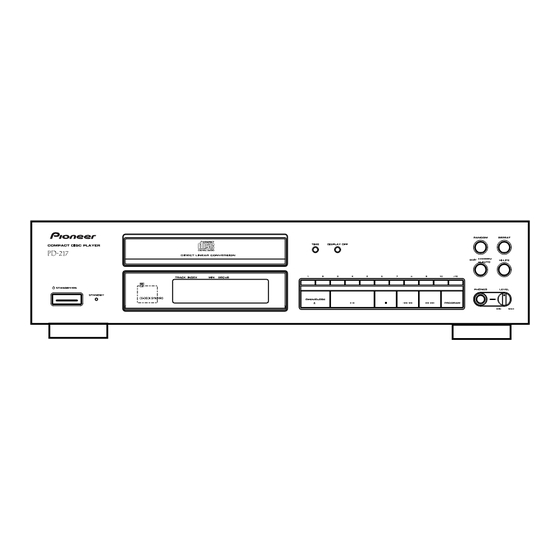
Page 32: Panel Facilities
8. PANEL FACILITIES 7 PANEL FACILITIES REMOTE CONTROL UNIT (PD-217 : Only) 4 5 6 78 90 RANDOM REPEAT COMPACT DISC PLAYER TIME DISPLAY OFF DIRECT LINEAR CONVERSION ¶ COMPU EDIT ¶¶ AUTO HI-LITE >10 TRACK INDEX SEC/dB Î STANDBY/ON PHONES LEVEL STANDBY...
Need help?
Do you have a question about the PD-117 and is the answer not in the manual?
Questions and answers