
Related Manuals for WFI E024


Summary of Contents for WFI E024
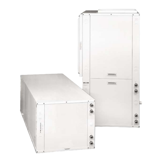
- Page 1 Geothermal/Water Source Heat Pumps • R-410A Refrigerant • 2 thru 6 Ton Installation Information Water Piping Connections Desuperheater Connections Electrical Startup Procedures Troubleshooting Preventive Maintenance IM2502 09/04...
-
Page 2: Model Nomenclature
E SERIES INSTALLATION MANUAL Model Nomenclature E 024 T L 0 0 1 N B D S S Family Vintage E Series R-410A A = Current Non-Standard Option Details Unit Capacity S = STD MBTUH Non-Standard Options Discharge Air Configuration S = No options T = Top (Vertical) 4 = FX10*... -
Page 3: Table Of Contents
E SERIES INSTALLATION MANUAL Table of Contents General Installation Information Water Piping and Condensate Closed Loop Ground Source Systems Open Loop Ground Water Systems Desuperheater Connection & Startup 10-11 Electrical Connections Electronic Thermostat Installation Setting Fan Speed Fan Performance Tables 14-15 Standard Microprocessor Control 16-18... -
Page 4: General Installation Information
E SERIES INSTALLATION MANUAL General Installation Information Safety Considerations Before performing service or maintenance operations on a system, turn off main WARNING: power switches to the indoor unit. If applicable, turn off the accessory heater power switch. Electrical shock could cause personal injury. Installing and servicing heating and air conditioning equipment can be hazardous due to system pressure and electrical components. -
Page 5: Installing Horizontal Units
Lockwasher MODEL E024, E030, E035 24.8 61.5 22.5 63.0 – E036, E040, E047, E048 27.8 70.5 25.5 72.0 29.9 E024-035 (4 hangers included) E058, E060 27.8 75.5 25.5 77.0 29.9 E036-072 (6 hangers included) E066, E072 27.8 80.5 25.5 82.0... -
Page 6: Water Piping And Condensate
E SERIES INSTALLATION MANUAL Duct System An air outlet collar is provided on vertical top flow units and all horizontal units to facilitate a duct connection (vertical bottom flow units have no collar). A flexible connector is recommended for discharge and return air duct connections on metal duct systems. -
Page 7: Water Quality
E SERIES INSTALLATION MANUAL Water Quality In ground water situations where scaling could be heavy or where biological growth such as iron bacteria will be pres- ent, a closed loop system is recommended. The heat exchanger coils in ground water systems may, over a period of time, lose heat exchange capabilities due to a buildup of mineral deposits inside. -
Page 8: Closed Loop Ground Source Systems
E SERIES INSTALLATION MANUAL Closed Loop Ground Source Systems Note: For closed loop systems with antifreeze protection, set SW2-2 to the “loop” position (see table on page 18). Once piping is completed between the unit, pumps and the ground loop (see figure below), final purging and charging of the loop is required. -
Page 9: Open Loop Ground Water Systems
E SERIES INSTALLATION MANUAL Open Loop Ground Water Systems Typical open loop piping is shown below. Always maintain water pressure in the heat exchanger by placing water control valves at the outlet of the unit to prevent mineral precipitation. Use a closed, bladder-type expansion tank to minimize mineral formation due to air exposure. - Page 10 E SERIES INSTALLATION MANUAL Desuperheater Connections A minimum 50-gallon water heater is required. For higher demand applications, use an 80-gallon water heater or two 50-gallon water heaters connected in a series as shown below. Electric water heaters are recommended. Make sure all local electrical and plumbing codes are met for installing a desuperheater.
-
Page 11: Desuperheater Connection & Startup
E SERIES INSTALLATION MANUAL Plumbing Installation 1. Inspect the dip tube in the water heater cold inlet for a check valve. If a check valve is present it must be removed or damage to the desuperheater circulator will occur. 2. Remove drain valve and fitting. 3. -
Page 12: Electrical Connections
E SERIES INSTALLATION MANUAL Electrical Connections General Be sure the available power is the same voltage and phase as that shown on the unit serial plate. Line and low voltage wiring must be done in accordance with local codes or the National Electric Code, whichever is applicable. Unit Power Connection Figure 13: Line Voltage 208-230/60/1 Control Box Connect the incoming line voltage wires to L1 and L2, or L1,L2, and... -
Page 13: Electronic Thermostat Installation
E SERIES INSTALLATION MANUAL Electronic Thermostat Position the thermostat subbase against the wall so that it is Figure 16: Thermostat Wiring level and the thermostat wires protrude through the middle of the subbase. Mark the position of the subbase mounting holes and 24VAC (Hot) drill holes with a 3/16-inch bit. -
Page 14: Fan Performance Tables
E SERIES INSTALLATION MANUAL Fan Performance Data ECM2 AIR FLOW DIP SWITCH SETTINGS MODEL SINGLE SPEED E024 0.50 E030 0.50 1000 1100 E035 0.50 1000 1175 1250 1050 1325 E040 0.50 1150 1250 1375 1475 1050 1250 1550 E047 0.50... - Page 15 E SERIES INSTALLATION MANUAL Fan Performance Data SPEED 0.00 0.05 0.10 0.15 0.20 0.25 0.30 0.35 0.40 0.45 0.50 0.60 0.70 0.80 0.90 1.00 E024 Max 1020 CFM High 1020 1003 984 Rated 700 Min 580 CFM E030 Max 1275 CFM...
-
Page 16: Standard Microprocessor Control
E SERIES INSTALLATION MANUAL Standard Microprocessor Control Features Startup The unit will not operate until all the inputs and safety controls are checked for normal conditions. At first power-up, a four-minute delay is employed before the compressor is energized. Component Sequencing Delays Components are sequenced and delayed for optimum space conditioning performance. - Page 17 E SERIES INSTALLATION MANUAL Standard Microprocessor Control Features Fan Speed Control A DIP switch on the E Series control allows field selection of 15% reduced fan speeds for cooling in the dehumidification mode or medium and high fan speeds for cooling in the normal mode. Note: Fan speed can change automatically only with an ECM Motor.
- Page 18 E SERIES INSTALLATION MANUAL Standard Microprocessor DIP Switches Prior to powering unit, ensure that all DIP switches on SW2 & SW3 are set properly according to the tables below. FACTORY SETUP DIP SWITCHES (SW3) DIP SWITCH DESCRIPTION OFF POSITION ON POSITION NUMBER Dual Capacity/Single-Speed Dual Capacity...
-
Page 19: Optional Fx10 Microprocessor Control
E SERIES INSTALLATION MANUAL Optional FX10 Microprocessor Control The Johnson Controls FX10 board is specifically designed for commercial heat pumps and provides control of the entire unit as well as input ports for N2 Open, LonTalk, BacNet communication protocols as well as an input port for a user interface. The user interface is an accessory item that can be used to aid in diagnostics and unit setup. -
Page 20: Unit Startup
E SERIES INSTALLATION MANUAL Unit Startup Before Powering Unit, Check The Following • High voltage is correct and matches nameplate. • Fuses, breakers and wire size correct. • Low voltage wiring complete. • Piping completed and water system cleaned and flushed. •... -
Page 21: Description Of Unit Operation
E SERIES INSTALLATION MANUAL Description of Unit Operation Heating Operation Heat, 1st Stage (Y1) The fan motor is started on low speed immediately, the loop pump is energized 5 seconds after the “Y1” input is re- ceived, and the compressor is energized on low capacity 10 seconds after the “Y1” input. The fan is switched to medium speed 15 seconds after “Y1”... -
Page 22: Operation Logic
E SERIES INSTALLATION MANUAL Lockout Conditions (continued) High Pressure This lockout mode occurs when the normally closed safety switch is opened momentarily (set at 600 PSI). Low Pressure This lockout mode occurs when the normally closed low pressure switch is opened for 30 continuous seconds (set at 40 PSI). -
Page 23: Unit Operating Parameters
E SERIES INSTALLATION MANUAL Unit Operating Parameters Single Speed Models COOLING - NO DESUPERHEATER ENTERING WATER SUBCOOLING SUCTION DISCHARGE SUPER WATER AIR TEMP WATER FLOW PRESSURE PRESSURE HEAT TEMP DROP °F TEMP °F GPM/TON 024-058 PSIG PSIG 024-058 RISE °F 122-130 220-235 13-19... - Page 24 E SERIES INSTALLATION MANUAL Dual Capacity Models FIRST STAGE OPERATION COOLING - NO DESUPERHEATER ENTERING WATER SUCTION DISCHARGE WATER AIR TEMP WATER FLOW SUPER PRESSURE PRESSURE TEMP DROP °F TEMP °F GPM/TON HEAT COOLING PSIG PSIG RISE °F 134-144 195-203 14-20 12-18 21-25...
-
Page 25: Pressure Drop & Recommended Flow Rates
CLOSED WELL UNIT 30° 50° 70° 90° 110° LOOP WATER E024 4.5 - 6 3 - 4 E030 5.5 - 7 4 - 5 E035 7 - 9 5 - 6 4 - 5 Lo cap 3 - 4 Lo cap... -
Page 26: Troubleshooting
E SERIES INSTALLATION MANUAL Troubleshooting Standard Microprocessor Controls To check the unit control board for proper operation: 1) Disconnect thermostat wires at the control board. 2) Jumper the desired test input (Y1, Y2, W, O or G) to the R terminal with the SW2-8 in the “OFF” position to simulate a thermostat signal. -
Page 27: Preventive Maintenance
E SERIES INSTALLATION MANUAL Preventive Maintenance Water Coil Maintenance 1. Keep all air out of the water. An open loop system should be checked to ensure that the well head is not allowing air to infiltrate the water line. Lines should always be airtight. 2. - Page 28 Type: Geothermal/Water Source Heat Pumps Size: 2 thru 6 Ton Document Type: Installation Manual WFI has a policy of continuous product research and Part Number: IM2502 development and reserves the right to change design Release Date: 09/04 and specifications without notice.
Need help?
Do you have a question about the E024 and is the answer not in the manual?
Questions and answers