
Subscribe to Our Youtube Channel
Summary of Contents for Danfoss dp710
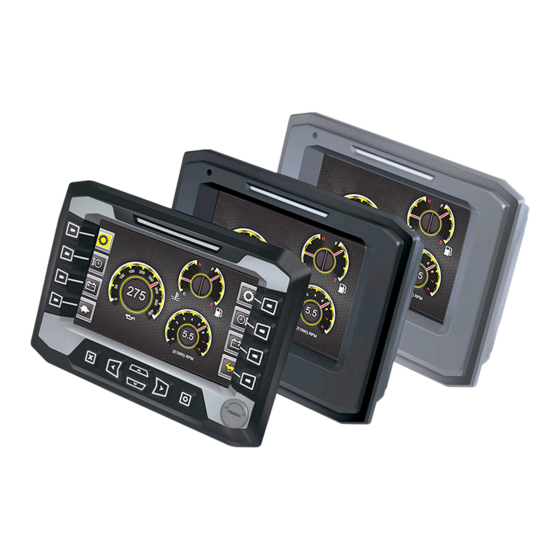
- Page 1 Technical Information PLUS+1® Mobile Machine Displays DP7XX Series powersolutions.danfoss.com...
- Page 2 November 2014 Added DP720 LCD statement; Corrected Pin Assignments callouts on image of back of Display March 2014 Changed note to warning December 2013 LCD option table added, changed Panel Mounting Kit part number October 2013 Various July 2013 Added section May 2013 First edition L1315553 | BC00000223en-US0504 © Danfoss | November 2016...
-
Page 3: Table Of Contents
LCD press and hold feature................................ 20 Installation DP700, DP710, DP720 dimensions............................21 DP730 dimensions..................................22 Two mounting options................................23 Flush mounting option................................23 Stand-alone on post mounting option..........................23 DP700, DP710, DP720 connectors pin assignments......................24 L1315553 | BC00000223en-US0504 | 3 © Danfoss | November 2016... - Page 4 Technical Information DP7XX Series Displays Contents DP730 connectors pin assignments............................25 Machine wiring guidelines................................. 26 Machine welding guidelines..............................26 L1315553 | BC00000223en-US0504 © Danfoss | November 2016...
-
Page 5: Dp7Xx Reference Literature
• How to upload and download tuning parameters • How to use the PLUS+1 ® Service Tool Latest version of technical literature Danfoss product literature is online at: http://powersolutions.danfoss.com/literature/ L1315553 | BC00000223en-US0504 | 5 © Danfoss | November 2016... -
Page 6: User Liability And Safety Statements
User liability and safety statements OEM responsibility The OEM of a machine or vehicle in which Danfoss products are installed has the full responsibility for all consequences that might occur. Danfoss has no responsibility for any consequences, direct or indirect, caused by failures or malfunctions. -
Page 7: Dp7Xx Series Displays
Anyone in receipt of this program may obtain the complete corresponding source code from Danfoss for a period of three years after the last shipment of this product and/or spare parts by going on line at http://www.danfoss.com... -
Page 8: Ordering Information
A—Model name Code Description DP700 PLUS+1 ® Mobile Machine Displays DP710 DP720 DP730 B—LCD options Code Description Value—Transmissive Standard—Transmissive High performance—Transmissive-Enhanced View TFT C—Touch screen options Code Description None Projective Capacitive touch L1315553 | BC00000223en-US0504 © Danfoss | November 2016... -
Page 9: Related Products
Mating connector kit with camera cable 11130520 USB cable (device only) 11130518 USB cable (device and host) 11130519 Only valid for DP710, DP720, and DP730. Connection tools Description Part numbers Crimp tool 16 to 20 AWG 10100744 Crimp tool 20 to 24 AWG... -
Page 10: Mounting Kit
GUIDE Professional Software (includes 1 year of software 11179523 updates, a single user license, Service and Diagnostic Tool and (annual renewal with 11179524 to keep the Screen Editor) software updates) L1315553 | BC00000223en-US0504 10 | © Danfoss | November 2016... -
Page 11: Inputs/Outputs
Input impedance with pull-down kΩ 13.2 ± 0.3 To 0 V Input impedance with pull-up kΩ 13.2 ± 0.3 To 5 V Input impedance with pull-up/down kΩ 7.02 ± 0.2 To 2.5 V L1315553 | BC00000223en-US0504 | 11 © Danfoss | November 2016... -
Page 12: Multifunction
4–20 mA input Description Unit Minimum Maximum Comment Range — Resolution μA — Worst case error ±(0.2 + I*3%) — Input impedance Ω 100 ± 2 To 0 V Shut-off current — L1315553 | BC00000223en-US0504 12 | © Danfoss | November 2016... -
Page 13: Encoder
Other than supporting memory sticks and computer connection, the DP7XX series display USB port does not support any other standard computer peripherals. L1315553 | BC00000223en-US0504 | 13 © Danfoss | November 2016... -
Page 14: Video
The use of a different power supply for the camera can create “noise” on the signal line which will affect its functionality. Real Time Clock (RTC) Parameter Units Backup Time month Drift s/day L1315553 | BC00000223en-US0504 14 | © Danfoss | November 2016... -
Page 15: Controller Area Network (Can) Specifications
The default baud rate is 250kbit. 1000 Maximum input voltage — — range Gateway channels PLUS+1 ® Service Tool can be connected to the CAN bus by using the following gateway channels. L1315553 | BC00000223en-US0504 | 15 © Danfoss | November 2016... - Page 16 Service Tool can be connected to the CAN bus by using the following gateway channels. Simultaneous usage gateway channels Channel Description CAN[0] and CAN[1] 1 or 4 CAN[1] 2 or 5 CAN[0] 3 or 6 No CAN port L1315553 | BC00000223en-US0504 16 | © Danfoss | November 2016...
-
Page 17: Memory
PLUS+1 ® Service Tool to extract the logged data. Accessing non-volatile or application log memory can delay the service tool scan. L1315553 | BC00000223en-US0504 | 17 © Danfoss | November 2016... -
Page 18: Product Ratings
˚C [˚F] -30 [-22] +80 [+176] — Ingress Protection (IP) rating Series Rating Comment DP700, DP710, DP720 IP67 With mating connector installed and sealing plugs in unused connections. DP730 Front: IP69K Rear: IP67 Warning Excessive high/low operating/storage temperatures can damage electronics. Damaged electronics can result in performance failure. -
Page 19: Testing Criteria
IEC 60068-2-38 Chemical Condition Rating Chemical resistance ISO 16750-5 Mechanical Condition Rating Vibration, resonance IEC 60068-2-6 Vibration, operation IEC 60068-2-64 Bump IEC 60068-2-29 Shock IEC 60068-2-27 Free fall IEC 60068-2-32 L1315553 | BC00000223en-US0504 | 19 © Danfoss | November 2016... -
Page 20: Maintenance Guidelines
The protective glass will break if hit with a hard or heavy object. If the protective glass is broken, remove the display from your machine then return the display to Danfoss to be serviced. Clean the display's housing and protective glass with a clean, soft, damp cloth, or mild dishwashing detergent because abrasive pads or solvents, including alcohol, benzene, and paint thinner can cause scratching and discoloration. -
Page 21: Installation
Technical Information DP7XX Series Displays Installation DP700, DP710, DP720 dimensions millimeters [inches] 9.90 235.20 [0.39] [ 9.26] 42.60 [1.68] 177.80 [ 7.00] REF 163.50 [ 6.44] 4X M4 75.00 ± 0.50 80.08 ± 0.50 [2.95 ± 0.02] [3.15 ± 0.02] 27.60 ±... -
Page 22: Dp730 Dimensions
161.90 [ 6.37] 4X M4 75.00 ± 0.50 80.08 ± 0.50 [2.95 ± 0.02] [3.15 ± 0.02] 27.60 ± 0.50 [1.09 ± 0.02] 75.00 ± 0.50 [2.95 ± 0.02] P200188 L1315553 | BC00000223en-US0504 22 | © Danfoss | November 2016... -
Page 23: Two Mounting Options
Technical Information DP7XX Series Displays Installation Two mounting options Flush mounting option Use the Danfoss panel mounting kit (Danfoss part number 11144800) to flush-mount into a dashboard. Panel cutout 4X 6 ± 0.25 [0.24 ± 0.01] 4 x 70˚ ± 1˚... -
Page 24: Dp700, Dp710, Dp720 Connectors Pin Assignments
Technical Information DP7XX Series Displays Installation DP700, DP710, DP720 connectors pin assignments C5-P1 C4-P5 C3-P5 C5-P8 C4-P1 C1-P1 C1-P12 C3-P1 P200 190 C5 M12 8-pin C3 M12 5-pin C4 M12 5-pin C1 Deutsch® DTM06 12-pin P200154 C6 pin Function C5 pin... -
Page 25: Dp730 Connectors Pin Assignments
C1-P6 CAN1 High +/(AIN/DIN) C5-P7 USB host D-/RS232 TxD C1-P7 CAN1 Low -/(AIN/DIN) C5-P8 USB host Vbus C1-P8 Sensor power/(AIN/ DIN) C1-P9 Sensor ground C1-P10 Multifunction-input C1-P11 Multifunction-input C1-P12 DOUT L1315553 | BC00000223en-US0504 | 25 © Danfoss | November 2016... -
Page 26: Machine Wiring Guidelines
Do not use electrical components to ground the welder. • Clamp the ground cable for the welder to the component that will be welded as close as possible to the weld. L1315553 | BC00000223en-US0504 26 | © Danfoss | November 2016... - Page 27 Technical Information DP7XX Series Displays L1315553 | BC00000223en-US0504 | 29 © Danfoss | November 2016...
- Page 28 Phone: +86 21 3418 5200 Danfoss can accept no responsibility for possible errors in catalogues, brochures and other printed material. Danfoss reserves the right to alter its products without notice. This also applies to products already on order provided that such alterations can be made without changes being necessary in specifications already agreed.
Need help?
Do you have a question about the dp710 and is the answer not in the manual?
Questions and answers