
Subscribe to Our Youtube Channel
Summary of Contents for TE LDM-1000
- Page 1 OPERATION MANUAL LDM-1000 LVDT/RVDT Signal Conditioning Module TE CONNECTIVITY SENSORS /// LDM-1000 OPERATION MANUAL P/N 09290100-000 REV. C 05/2016 Page 1...
-
Page 2: Table Of Contents
4. 4. 4. 5. Oscillator Drive Capability ..........................7 4. 6. Setting the Amplifier Gain ..........................7 Dimensions and Wiring Terminals .........................8 Connection Diagrams ............................9 Calibration Procedure ..........................10 TE CONNECTIVITY SENSORS /// LDM-1000 OPERATION MANUAL P/N 09290100-000 REV. C 05/2016 Page 2... -
Page 3: Introduction
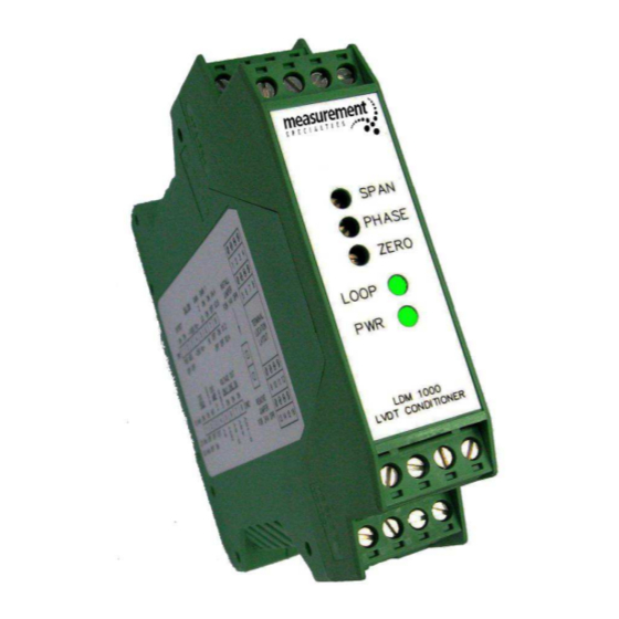
LVDT/RVDT Signal Conditioning Module 1. Introduction The LDM-1000 is an extremely versatile LVDT/RVDT (Linear or Rotary Variable Differential Transformer) signal conditioning module. The module supplies an AC sine wave excitation to the LVDT or RVDT, and demodulates, filters, and amplifies the output. -
Page 4: Product Description
An internal jumper allows changing the input voltage range from 18~30 VDC to 10~18 VDC. A green LED on the front panel lights up when the LDM-1000 is powered on. A second green LED light indicates that the loop current is flowing. -
Page 5: Supply Voltage
4. 1. Supply Voltage The LDM-1000 supply voltage range is 18~30 VDC with the JP1 jumper in the storage position (as shipped position). Only this range (18~30VDC) can be used for 4-20mA output operation. The operating voltage may be changed to 10~18 VDC by installing internal jumper JP1 across both pins. -
Page 6: Internal Switches
LDM-1000 LVDT/RVDT Signal Conditioning Module 4. 2. Internal Switches There are two internal DIP switch sets (SW1 and SW2) on the PC board assembly of the LDM-1000. The tables below explain the switch positions and functions. Switch Set SW1 Function:... -
Page 7: Oscillator 'Sync' Mode
The Oscillator ‘Sync’ mode setting will depend on the number of LDM-1000’s and transducers in your system, and their physical locations. For a single LVDT or RVDT system you will be running the LDM-1000 in the Master (INT) mode. For systems with multiple LDM-1000’s, especially when they are co-located, and/or the interconnect cables between the LDM-1000’s and the... -
Page 8: Dimensions And Wiring Terminals
LDM-1000 LVDT/RVDT Signal Conditioning Module 5. Dimensions and Wiring Terminals TE CONNECTIVITY SENSORS /// LDM-1000 OPERATION MANUAL P/N 09290100-000 REV. C 05/2016 Page 8... -
Page 9: Connection Diagrams
LDM-1000 LVDT/RVDT Signal Conditioning Module 6. Connection Diagrams TE CONNECTIVITY SENSORS /// LDM-1000 OPERATION MANUAL P/N 09290100-000 REV. C 05/2016 Page 9... -
Page 10: Calibration Procedure
DC voltmeter, and a power supply (see “Supply Voltage” under the “Initial Setup Procedure” section of this manual) to the LDM-1000. Turn the power on and allow a 15 minute warm-up. Follow the procedure below: Disconnect the LVDT/RVDT primary wire from Terminal 1 of P1. - Page 11 TE Connectivity‘s obligations shall only be as set forth in TE Connectivity‘s Standard Terms and Conditions of Sale for this product and in no case will TE Connectivity be liable for any incidental, indirect or consequential damages arising out of the sale, resale, use or misuse of the product.
Need help?
Do you have a question about the LDM-1000 and is the answer not in the manual?
Questions and answers