Sinclair SMH-100IRA? SMH-140IRA Original Instructions Manual
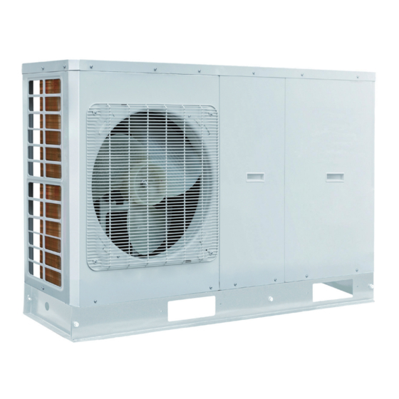
Monoblock inverter air to water heat pumps
Hide thumbs
Also See for SMH-100IRA? SMH-140IRA:
- Operation manual (38 pages) ,
- Control and operation manual (36 pages)
Table of Contents
Advertisement
Quick Links
Download this manual
See also:
Operating Manual
Advertisement
Table of Contents

Related Manuals for Sinclair SMH-100IRA? SMH-140IRA


Summary of Contents for Sinclair SMH-100IRA? SMH-140IRA
- Page 1 MONOBLOCK INVERTER AIR TO WATER HEAT PUMPS SMH-100IRA SMH-140IRA...
- Page 2 “Original instructions” ...
-
Page 3: Table Of Contents
Contents 1 Instruction to Users..................1 2 Safety Considerations ................2 3 Diagram of the Operating Principle ............5 4 Operating Principle of the Unit..............6 5 Nomenclature ..................8 6 Installation Example ................9 7 Main Components ................11 8 Installation Guideline of the Unit ............13 9 Remote Air Temperature Sensor ............17 10 Thermostat ..................18 11 2-Way Valve ..................18... -
Page 4: Instruction To Users
Air-to-water Heat Pump Monoblock 1 Instruction to Users Thank you for choosing our air to water heat pumps. Please read this manual carefully before installation and use the unit correctly according to the following procedure. After receipt of the unit, check it for appearance, unit model compared with your desire and ◆... -
Page 5: Safety Considerations
Air-to-water Heat Pump Monoblock 2 Safety Considerations Please read the following contents carefully before operating. WARNING ■ Once abnormality like burning ■ Don't operate the unit with wet ■ Before installation,please smell occurs, please cut off hand. see if the voltage of local the power supply immediately place accords with that on and then contact with service... - Page 6 Air-to-water Heat Pump Monoblock ■ Earthing: the unit must be ■ N e v e r i n s e r t a n y f o r e i g n ■ Don't attempt to repair the unit earthed reliably ! The earthing m a t t e r i n t o u i n t t o a v o i d by yourself.
- Page 7 Air-to-water Heat Pump Monoblock (4) The On/off in the instruction is for the operation to on and off button of PCB for users; cut off power means to stop supplying power to the unit. (5) Don’t directly expose the unit under the corrosive ambient with water or dampness. (6) Don’t operate the unit without water in water tank .The air outlet/inlet of unit can not be blocked by other objects.
-
Page 8: Diagram Of The Operating Principle
Air-to-water Heat Pump Monoblock 3 Diagram of the Operating Principle Name Name Name Name Solar system inlet Inverter compressor Solenoid valve Water filter temperature sensor Inlet temperature Discharge temperature EXV 2 sensor (plate heat Water separator sensor exchanger) High-pressure switch Low pressure sensor Safety valve 2-way Valve 1... -
Page 9: Operating Principle Of The Unit
Air-to-water Heat Pump Monoblock 4 Operating Principle of the Unit DC Inverter Air to Water Heat Pump is composed of the unit,FCU and water tank. Operation functions: (1) Cooling; (2) Heating; (3) Water heating; (4) Cooling +water heating; (5) Heating+ water heating; (6) Emergency mode;... - Page 10 Air-to-water Heat Pump Monoblock user can set the priority of these two modes based on the needs. The default priority is heat pump. That is under the default setting, if heating mode exists together with the water heating mode, the heat pump gives priority to heating.
-
Page 11: Nomenclature
Air-to-water Heat Pump Monoblock 5 Nomenclature Model Line-Up Capacity Model Name Power supply Heating Cooling 220-240V,~,50Hz SMH-100IRA SMH-140IRA 14.5 380-415V,3N~,50Hz 14.2 Note: Capacities and power inputs are based on the following conditions: Indoor Water Temperature 30°C/35°C,Outdoor Air Temperature 7°C DB/6°C WB; Capacities and power inputs are based on the following conditions: Indoor Water Temperature 23°C/18°C,Outdoor Air Temperature 35°C DB/24°C WB. -
Page 12: Installation Example
Air-to-water Heat Pump Monoblock 6 Installation Example CASE 1: Connecting Heat Emitters for Heating and Cooling(Under floor loop,Fan Coil Unit,and Radiator) Note: ① The two-way valve is very important to prevent dew condensation on the floor and Radiator while cooling mode; ②... - Page 13 Air-to-water Heat Pump Monoblock Note: ① In this case, three-way valve should be installed and should be complied with installation of this manual; ② Sanitary water tank should be equipped with internal electric heater to secure enough heat energy in the very cold days; CASE 3 : Connecting Solar thermal system Two-way valve is very important to prevent dew condensation on the floor and Radiator while cooling mode.
-
Page 14: Main Components
Air-to-water Heat Pump Monoblock Notes: 1)Two-way valve is very important to prevent dew condensation on the floor and Radiator while cooling mode. 2) 3-Way valve 1 is controlled by user,while the pool pump is actived, 3-Way valve 1 switches to pool loop;while the pool pump is shuted down,3-Way valve 1 switches to under floor/FCU loop. - Page 15 Air-to-water Heat Pump Monoblock SMH-140IRA Control Box Safety Valve DC Fan Motor Air Vent Electric Heater Flow Switch Expansion Tank Water Pump Compressor Plate Heat Exchanger Flash Tank...
-
Page 16: Installation Guideline Of The Unit
Air-to-water Heat Pump Monoblock 8 Installation Guideline of the Unit 8.1 Instruction to installation (1) Installation of the unit must be in accordance with national and local safety codes. (2) IInstallation quality will directly affect the normal use of the air conditioner unit. The user is prohibited from installation. - Page 17 Air-to-water Heat Pump Monoblock SMH-140IRA 1390 8.2.3 Space requirements for installation 2000 > 8.2.4 Precautions on installation of the Monobloc Unit (1) When moving the monobloc unit, it is necessary to adopt 2 pieces of long enough rope to hand the unit from 4 directions.
- Page 18 Air-to-water Heat Pump Monoblock 8.3 Water Volume and Pump Capacity (with pump) /min Note: during operation, the water pump will adjust its output based on the actual load.
- Page 19 Air-to-water Heat Pump Monoblock 8.4 Water Volume and Expansion Vessel Pressure Maximum total water volume(liter) Note: ① The expansion vessel is 10 liter and 1bar pre-pressurized; ② Total water volume of 280 liter is default; if total water is changed because of installation condition, the pre-pressure should be adjusted to secure proper operation;...
-
Page 20: Remote Air Temperature Sensor
Air-to-water Heat Pump Monoblock 0.0324 0.0359 0.0396 0.0434 9 Remote Air Temperature Sensor Front side Back side Remote Air Temperature Sensor 1.5 Meters Doors Remote Air Environment CN15 Temp sensor Electric box Note: ① Distance between the monobloc unit and the remote air temperature senor should be less than 15 meter due to length of the connection cable of remote air temperature sensor;... -
Page 21: Thermostat
Air-to-water Heat Pump Monoblock applied; ⑤ Remote air temperature sensor should be installed where space heating is mainly applied; ⑥ After the remote air temperature sensor is installed, it should be set to “With” through the wired controller so as to set the remote air temperature to the control point. 10 Thermostat Installation of the thermostat is very similar to that of the remote air temperature sensor. -
Page 22: 12 3-Way Valve
Air-to-water Heat Pump Monoblock How to Wire 2-Way Valve: Follow steps below to wire the 2-way valve. Step 1. Uncover the front cover of the unit and open the control box. Step 2. Find the terminal block and connect wires as below. 2-Way Valve 2 2-Way Valve 1 WARING! -
Page 23: Wired Controller
Air-to-water Heat Pump Monoblock WARING! ① The 3-way valve should select water tank loop when electric power is supplied to wire (OFF) and wire (N). ② The 3-way valve should select under floor loop when electric power is supplied to wire (ON) and wire (N). -
Page 24: Charging And Discharging Of Refrigerant
Air-to-water Heat Pump Monoblock 16 Charging and Discharging of Refrigerant The unit has been charged with refrigerant before delivery. Overcharging or undercharging will cause the compressor to run improperly or be damaged. When refrigerant is required to be charged or discharged for installation, maintenance and other reasons, please follow steps below and nominal charged volume on the nameplate. -
Page 25: Installation Of Insulated Water Tank
Air-to-water Heat Pump Monoblock With siphon tube No siphon tube 17 Installation of Insulated Water Tank 17.1 Installation measure The water tank should keep a horizontal distance of 5 meters and a vertical distance of 3 meters with the main unit. It allowed to be installed in the room. The standing type water tank must be installed erectly on the ground/floor and never be suspended. - Page 26 Air-to-water Heat Pump Monoblock 17.2 Connection of waterway system (1) If connection between the water tank and the monobloc unit should go through the wall, drill a hole φ70 for pass of circulating water pipe. (2) Preparation of pipelines: circulating water outlet/inlet pipe must be hot water pipe and PPR pipe with nominal outer diameter of dn25 and S2.5 series (wall thickness of 4.2mm) are recommended.
-
Page 27: Electric Wiring Work
Air-to-water Heat Pump Monoblock ③ Waterway pipelines can’t be installed until water heater unit is fixed. Do not let dust and other sundries enter into pipeline system during installation of connection pipes. ④ After connection of all waterway pipelines, perform leakage test firstly. After that, perform heat preservation of waterway system;... - Page 28 Air-to-water Heat Pump Monoblock local laws and regulations. ⑤ Ensure safe grounding and the grounding wire shall be connected with the special grounding equipment of the building and must be installed by professional technicians. ⑥ The specifications of the breaker and power cable listed in the table above are determined based on the maximum power (maximum amps) of the unit.
-
Page 29: Wring Diagram
Air-to-water Heat Pump Monoblock 18 Wring Diagram 18.1 Control Board (1) Main Board (AP2): SMH-100IRA; SMH-140IRA ENTH AC-N AC-L VA-1 HEAT ENTH-PRESS L-PRESS H-PRESS COM-ESPE2 PWR1 DC-MOTOR0 T-SENSOR3 DC-MOTOR1 T-SENSOR2 Silk Screen Specification AC_N Neutral wire input of power supply AC_L Live wire input of power supply 4-way valve... - Page 30 Air-to-water Heat Pump Monoblock (2)Main Board (AP1): SMH-100IRA; SMH-140IRA HEAT1 BAN-HEAT 2V1_ON 2V2_ON 3V1_ON 3V2_ON OTHER_HEAT_ AC-L RR RUNH HEAT2 2V1_OFF 2V2_OFF 3V1_OFF 3V2_OFF OTHER_HEAT_DCOUT 220V OTHER_HEAT_DCIN CN33 COM-OUT TR-IN CN31 INDOOR_PUMP CN18 TR-OUT2 POOL_PUMP TR-OUT1 SOLOR_PUMP T-SEN13 SW_INDOOR SW_SOLAR T-SEN12 SW_POOL T-SEN10...
-
Page 31: Sensor
Air-to-water Heat Pump Monoblock 2V1_ON Electric magnetic 2-way valve1 is normally open. 2V2_OFF Electric magnetic 2-way valve2 is normally closed. 2V2_ON Electric magnetic 2-way valve2 is normally open. 3V1_OFF Electric magnetic 3-way valve1 is normally closed. 3V1_ON Electric magnetic 3-way valve1 is normally open. 3V2_OFF Electric magnetic 3-way valve2 is normally closed. - Page 32 Air-to-water Heat Pump Monoblock (3) Drive Board (AP4): SMH-100IRA G-OUT L1- 2 P-OU T L2-1 DC-BUS 1 L1-1 AC-L COMM L2-2 COMM1 Silk Screen Introduction AC-L Live line input of the drive board Neutral line input of the drive board L1-1 To PFC inductor brown line L1-2...
- Page 33 Air-to-water Heat Pump Monoblock (4) Drive Board (AP4): SMH-140IRA Silk Screen Introduction COMM Communication interface [1-3.3V, 2-TX, 3-RX, 4-GND] Switch power interface [1-310VDC, 3-GND] Connector to filter L1-F Connector to filter L2-F Connector to filter L3-F Connector to L1-1 OF PFC reactor 1 Connector to L2-1 OF PFC reactor 2 Connector to L3-1 OF PFC reactor 3 Connector to L3-2 of PFC reactor 3...
- Page 34 Air-to-water Heat Pump Monoblock (5) Filter Board (AP3): SMH-100IRA AC-N AC-L N-OUT1 N-OUT L -OUT Silk Screen Introduction AC-N Neutral line of the power supply for the main unit AC-L Live line of the power supply for the main unit Neutral line output of the filter board (to the drive board) N-OUT Neutral line output of the filter board (to the main board )
- Page 35 Air-to-water Heat Pump Monoblock (6) Filter Board (AP3): SMH-140IRA Silk Screen Introduction Connector to power supply output line AC-L1 Connector to power supply output line AC-L2 Connector to power supply output line AC-L3 Connector to power supply neutral line AC-N Connector to the grounding line E , reserved Connector to power supply neutral line N-F (mainboard AC-N) Connector to power supply output line L3-F (drive board L3-F)
-
Page 36: High Pressure Sensor
Air-to-water Heat Pump Monoblock 18.2 Electric Wiring 18.2.1 Wiring principle Refer to Section 16.4. 18.2.2 Electric wiring design Wiring diagram: monobloc unit. SMH-100IRA ◆ CODE NAME Main Board Only For RT6 Power Indoor unit Main Board AC-L Outdoor unit Main Board Filter Board AC-N L-OUT... -
Page 37: Filter
Air-to-water Heat Pump Monoblock 18.2.3 Terminal Board SMH-100IRA ◆ SMH-140IRA ◆... -
Page 38: Commissioning
Air-to-water Heat Pump Monoblock 19 Commissioning 19.1 Check before startup For safety of users and unit, the unit must be started up for check before debugging. The procedures are as below: The following items shall be performed by qualified repair persons. Confirm together with the sales engineer, dealer, installing contractor and customers for the following items finished or to be finished. -
Page 39: Test Run
Air-to-water Heat Pump Monoblock 19.2 Test run Test run is testing whether the unit can run normally via preoperation. If the unit cannot run normally, find and solve problems until the test run is satisfactory. All inspections must meet the requirements before performing the test run. -
Page 40: Daily Operation And Maintenance
Air-to-water Heat Pump Monoblock 20 Daily Operation and Maintenance In order to avoid damage of the unit, all protecting devices in the unit had been set before delivery, so please do not adjust or remove them. For the first startup of the unit or next startup of unit after long-period stop (above 1 day) by cutting off the power, please electrify the unit in advance to preheat the unit for more than 8 hours. - Page 42 The value GWP: 2088 GWP = Global Warming Potential In case of quality problem or other please contact your local supplier or authorized service center. Emergency number: 112 PRODUCER SINCLAIR CORPORATION Ltd. 1-4 Argyll St. London W1F 7LD Great Britain www.sinclair-world.com This product was manufactured in China (Made in China).
Need help?
Do you have a question about the SMH-100IRA? SMH-140IRA and is the answer not in the manual?
Questions and answers