
Related Manuals for Mercedes-Benz E55 1996

Summary of Contents for Mercedes-Benz E55 1996
- Page 1 Mercedes E55, E430, E420, and E320 (W210) 1996 - 2002 Front Big Brake Upgrade 98-560-1450-03 12/14/09...
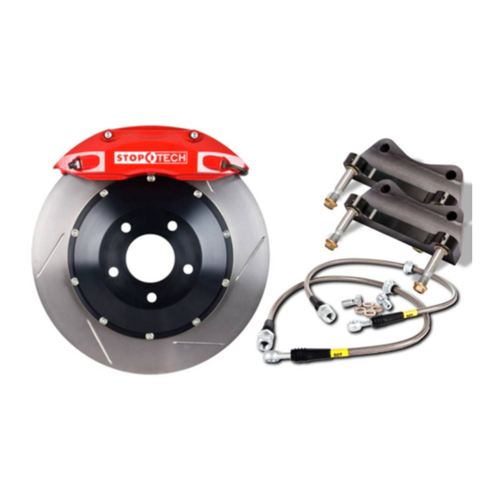
- Page 2 Mercedes E-Class Big Brake Kit This is a representative photograph. The actual components in your kit may appear slightly different. This kit contains the following: 1 pair of ST-40, 4 piston calipers sized specifically for the Mercedes E-Class 1 set of high performance brake pads 1 pair of either 332 X 32mm rotors or 355 X 32mm rotors, mounted to anodized billet 7075-T6 aluminum hats, using floating drive pins and Inconel anti-rattle hardware...
-
Page 3: Wheel Spacers
APPLICATION DISCLAMER Caliper Clearance Most 17” wheels will clear the outer diameter of the caliper of the 332mm kit and most 18” wheels will clear the 355mm kit. However, the more critical clearance is the gap between the spokes of the wheel and the face of the caliper. -
Page 4: Important Notices
Important Notices Wheel Fitment: Do not assume your wheels will fit. An outline drawing of your StopTech Big Brake kit is available on our website at http://www.stoptech.com. Measure the distance from the outer face of your stock caliper to the inner face of your wheel spokes, or make a template according to the instructions on the website and determine if a wheel spacer may be necessary. - Page 5 Mercedes E-Class Front Axle Kit Please, believe us, it will be better to read and understand this ENTIRE Installation Manual, including the included Break-in Procedures before starting the installation. Safety Notice Improper handling of a vehicle, especially while raised and supported by jack stands, ramps or other mechanical means can cause serious bodily injury or even death.
- Page 6 - DOT 3 or 4 Brake Fluid. Check manufactures’ recommendation for compatibility. StopTech recom- mends flushing brake fluid every 1-2 years, or more often under severe usage conditions. If not done recently, the installation of a brake kit is an excellent opportunity to refresh your brake fluid. Additional items you may need include: - Adhesive backed lead wheel weights Caliper, Hat and Bracket Finish Disclaimer:...
- Page 7 Step 1 (continued) Note: All Photographs Show Right Side Installation Unless Noted Otherwise. After securing the vehicle at a convenient height, remove the front wheels. Note: If you remove the bottom lug bolt last while holding the bottom of the tire, it will lessen the chances of the wheel tilting on it’s own and make removal easier.
- Page 8 Step 2 (continued) Use an 11mm flare wrench to loosen the hard line fitting from the stock brake line. Once the line has been loosened with the flare wrench, you may use a stubby 11mm wrench to finish disconnecting the hard line fitting.
- Page 9 Step 3 Remove Pad Wear Sensor Pad wear sensor The Mercedes uses a sensor at each caliper to notify the driver when a pad is in need of replacement. This sensor needs to be removed and secured out of the way so that it does not provide a false indication.
- Page 10 Step 3 (continued) Remove Pad Wear Sensor Pull the sensor and harness back behind the steering knuckle and secure firmly with several Ty-Wraps. Make sure the harness does not rub on any moving suspension components.
- Page 11 Step 4 Remove Stock Caliper & Rotor The stock brake line passes through a suspen- sion component and is held in place with a rubber grommet. Use a flat blade screwdriver to push this grommet loose. Next, feed the brake line through the suspension component in preperation for removing the caliper and line from the car.
- Page 12 Step 5 Install Caliper Bracket Install the caliper adapter bracket to the steer- ing knuckle using the stock caliper bolts. Place a few drops of the supplied Loctite thread locking compound on the ends of the caliper bolts before installing them. The pre-installed studs face forward, and the bracket mounts on the outboard side of the mounting lugs, as shown.
- Page 13 Step 6 (continued) Install hat and rotor assembly and secure in place with a 5mm Allen rotor retaining screw. It’s a good idea to place a dab of anti-seize paste on the threads of the screw prior to installing. Do not over tighten this screw. Tighten with 5mm Allen wrench Be sure the rotor assemblies are on the correct side of the car.
- Page 15 Caliper Component Identification Bolt-in Bridge Pad Retaining Clip Cross Over Tube Bleed Screw Bridge Bolts Use a light film of Anti-Sieze on Bridge Bolt shaft and threads The ST-40 caliper uses a Porsche style pad. The Friction Materials Standards Institute (FMSI) number for the pad backing plate D372 Please see the FAQ section of our website for further pad interchange information.
- Page 16 Step 7 Install Caliper and Pads - Determine the left and right side calipers. The calipers are marked on each box. As a check, the bleed screws always go to the top of the caliper. Remove the 2 bolts holding the caliper bridge using a 5mm Allen wrench. Remove the caliper bridge taking note of the direction it is installed in and the correct location of the pad retaining wire clip, which typically, but not always, stays attached to the bridge.
- Page 17 Step 7 (Continued) Install the caliper onto the adapter bracket studs with the bleed screws on the top side of the caliper. Slide the caliper over the mounting studs, making sure it is square and evenly started on both studs. It may necessary to gently tap the caliper into position with a non-marring hammer or mallet.
- Page 18 Step 7 (continued) Install the bridge by sliding it into position and rocking it until one of the bolt holes lines up. Be sure the bridge is slid straight and parallel into the caliper body opening. (See Page 15 for detailed bridge directions.) Note: The bridge is directional and the “air- scoop”...
- Page 19 Step 8 Attach the stainless brake line Route the brake line along the same path as the original stock brake line, passing it through the suspension component and rubber grommet. Do not install the brake lines twisted. Install the banjo bolt into the caliper with a copper washer on each side of the Banjo fitting on the brake line and torque to 14 lb-ft with a 12mm wrench.
- Page 20 Install a washer over the end of the stainless brake line before inserting it into the bracket from below. Remove the rubber cap from the hard line and screw the hard line fitting into the new stain- less brake line by hand for a few turns before tightening with an 11mm flare wrench.
- Page 21 Step 9 Bleed Brakes Complete installation on both sides of the vehicle before bleeding the system. Note: The calipers and lines will need to fill with fluid, quickly draining the master cylinder reservoir. Keep a close watch on the fluid level when initially bleeding the system. Do not allow the master cylinder reservoir to run dry and draw in air.
- Page 22 Step 10 Re-install wheels Check wheel to caliper clearance before installing wheels! Note: Some wheels are balanced on the inside with adhesive backed lead. If the lead is on the outboard edge behind the spokes, it may interfere with the caliper. If necessary note weight and location and place a new piece of the same weight further inboard or outboard to clear the cali- per.
- Page 23 AeroRotor Installation & Break-in Procedure READ THIS NOW FAILURE TO READ, UNDERSTAND AND FOLLOW THESE PROCEDURES WILL CAUSE PER- MANANT DAMAGE TO YOUR BRAKE ROTORS AND KEEP THE SYSTEM FROM WORKING AT IT’S FULL CAPACITY. The majority of brake system problems are due to improper installation and/or break-in of the rotors and pads.
- Page 24 Rotor and Pad Break-in (continued) Note- Bedding of pads should not be done in wet weather or wet road conditions. After completeing installation, make a series of 10 stops from 60 to 5-10 MPH. At the end of each stop, immediately accelerate to 60 again for the next stop. Run all stops in one cycle. During the 60 to 5-10 MPH series of stops, the exact speed is not critical.
- Page 25 Thank you for selecting StopTech, we realize you had a choice in selecting a big brake upgrade for your vehicle and know you’ll be happy with our system. We proudly support our fine products. For any assistance or questions, please contact our Customer Service Departmant (310) 218-1091 or e-mail us at support@stoptech.com.
Need help?
Do you have a question about the E55 1996 and is the answer not in the manual?
Questions and answers