Philips MCM190 Service Manual
Hide thumbs
Also See for MCM190:
- Manual del usuario (19 pages) ,
- Manuale per l'utente (19 pages) ,
- User manual (19 pages)
Table of Contents
Advertisement
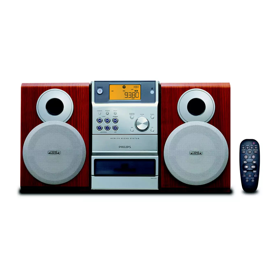
Micro System
TABLE OF CONTENTS
Handling chip components ............................................................ 1-1
Leadfree and safety information ................................................... 1-2
Technical specification .................................................................. 2-1
Service test program ..................................................................... 2-1
Service measurement setup ......................................................... 2-2
Connections and controls ..................................................... 3-1...3-2
Disassembly diagram ............................................................ 4-1...4-2
Set block diagram ......................................................................... 5-1
Set wiring diagram ........................................................................ 5-2
Display and key board
circuit diagram .......................................................................... 6-1
layout diagram .......................................................................... 6-2
Main and AC power board
circuit diagram. ................................................................. 7-1...7-2
layout diagram (component side) ............................................. 7-3
layout diagram (copper side) ................................................... 7-4
©
Copyright 2005 Philips Consumer Electronics B.V. Eindhoven, The Netherlands
All rights reserved. No part of this publication may be reproduced, stored in a retrieval
system or transmitted, in any form or by any means, electronic, mechanical, photocopying,
or otherwise without the prior permission of Philips.
Published by LX 0650 Service Audio
Version 1.0
Printed in The Netherlands
Subject to modification
MCM190, MCM195
Cassette board
circuit diagram .......................................................................... 8-1
layout diagram .......................................................................... 8-2
tape deck adjustment ............................................................... 8-2
Exploded view (main set) .............................................................. 9-1
Mechanical partslist ....................................................................... 9-2
Electrical partslist .............................................................. 10-1...10-2
all versions
© 3141 785 30200
Advertisement
Table of Contents

Related Manuals for Philips MCM190


Summary of Contents for Philips MCM190
-
Page 1: Table Of Contents
(copper side) ........... 7-4 © Copyright 2005 Philips Consumer Electronics B.V. Eindhoven, The Netherlands All rights reserved. No part of this publication may be reproduced, stored in a retrieval system or transmitted, in any form or by any means, electronic, mechanical, photocopying, or otherwise without the prior permission of Philips. -
Page 2: Handling Chip Components
1 - 1 HANDLING CHIP COMPONENTS... - Page 3 1 - 2...
-
Page 4: Service Test Program
2 - 1 SERVICE TEST PROGRAM... -
Page 5: Service Measurement Setup
2 - 2 SERVICE MEASUREMENT Tuner FW Bandpass LF Voltmeter 250Hz-15kHz e.g. PM2534 e.g. 7122 707 48001 RF Generator e.g. PM5326 S/N and distortion meter e.g. Sound Technology ST1700B Use a bandpass filter to eliminate hum (50Hz, 100Hz) and disturbance from the pilottone (19kHz, 38kHz). Tuner AM (MW,LW) Bandpass LF Voltmeter... -
Page 6: Connections And Controls
3 - 1 CONNECTION AND CONTROLS... - Page 7 3 - 2 CONNECTION AND CONTROLS...
-
Page 8: Disassembly Diagram
4 - 1 DISASSEMBLY DIADRAMS STEP A : Remove Back Cabinet - A1 : Remove 2 screws (SP3x12) - A2 : Remove 4 screws (SP3x10) - A3 : Remove 2 screws (K3x10) - A4 : Remove 2 screws (K3x10) STEP B : Remove CD Tray and Mains board - B1: Remove 4 screws (SP3x12) - Page 9 4 - 2 DISASSEMBLY DIADRAMS STEP C : Remove Main PCB Assy - Remove 3 screws (SP3x8) STEP D : Remove LCD PCB from Front Cabinet - E1 : Remove 10 screws (SP2.6x8) STEP E : Remove Tape Deck - H : Remove 4 screws (SP3x8)
-
Page 10: Set Block Diagram
5 - 1 SET BLOCK DIADRAM... -
Page 11: Set Wiring Diagram
5 - 2 5 - 2 SET WIRING DIAGRAM... -
Page 12: Circuit Diagram
6 - 1 6 - 1 CIRCUIT DIAGRAM - DISPLAY AND KEY BOARD... -
Page 13: Layout Diagram (Component Side)
6 - 2 6 - 2 LAYOUT DIAGRAM - DISPLAY AND KEY BOARD COMPONENT SIDE COPPER SIDE... - Page 14 7 - 1 7 - 1 CIRCUIT DIAGRAM - MAIN BOARD (1)
- Page 15 7 - 2 7 - 2 CIRCUIT DIAGRAM - MAIN BOARD (2)
-
Page 16: Layout Diagram (Copper Side)
7 - 3 7 - 3 LAYOUT DIAGRAM - MAIN AND POWER PCB (TOP VIEW) - Page 17 7 - 4 7 - 4 LAYOUT DIAGRAM - MAIN AND POWER PCB (BOTTOM VIEW)
- Page 18 8 - 1 8 - 1 CIRCUIT DIAGRAM - CASSETTE BOARD 1709 T701 R IN 1725 T721 L IN PLAY RECORD 3723 3722 T702 1707 3701 T705 + TAPE 100R 3749 3748 2707 2706 T707 R OUT 220u 3707 3726 T708 L OUT 470k...
- Page 19 8 - 2 8 - 2 LAYOUT DIAGRAM - CASSETTE BOARD 71 A 1 2729 C 5 3733 B 2 9756 C 3 72 D 5 2730 D 1 3734 D 5 9757 D 3 73 A 5 2731 C 1 3735 D 3 9759 D 4 74 A 1...
- Page 20 9 - 1 9 - 1 EXPLODED VIEW DIAGRAM record play reverse forward stop/open pause 13-18...
-
Page 21: Mechanical Partslist
9 - 2 ACCESSORIES MCM190 MCM195/37 9940 000 00509 9940 000 00509 AM LOOP ANT 9940 000 01589 9940 000 01589 REMOTE CONTROL 9940 000 01591 9940 000 02723 SPEAKER BOX ASSY MECHANICAL PARTS LIST MCM190 MCM195/37 9940 000 01662... -
Page 22: Electrical Partslist
10 - 1 ELECTRICAL PARTS LIST MAIN PWB ASSEMBLY CD / MP3 PART IC101 9940 000 01594 IC, TC94A58FAG-253 IC102 9940 000 01593 IC, TA2157FN IC103 9940 000 01592 IC, M24C01-W 1K EEPROM IC104 9940 000 01595 IC, D9258PH MOTOR DRIVER IC106 9940 000 01596 IC, XC61CN4702PR RESET... - Page 23 DISPLAY PWB ASSEMBLY IC901 9940 000 01623 IC, ET1621COB LCD DRIVER IRM901 9940 000 01622 IR RECEIVER GR-MF902V0 LCD901 9940 000 01624 LCD 81066TT/H(MCM190 LCD) LED901 9940 000 01625 LED LE543Y2DE-3F-01-S Q901 9940 000 02707 TRANSISTOR, 3DA8050 S900 9940 000 01626...
Need help?
Do you have a question about the MCM190 and is the answer not in the manual?
Questions and answers