Table of Contents
Advertisement
Available languages
Available languages
Quick Links
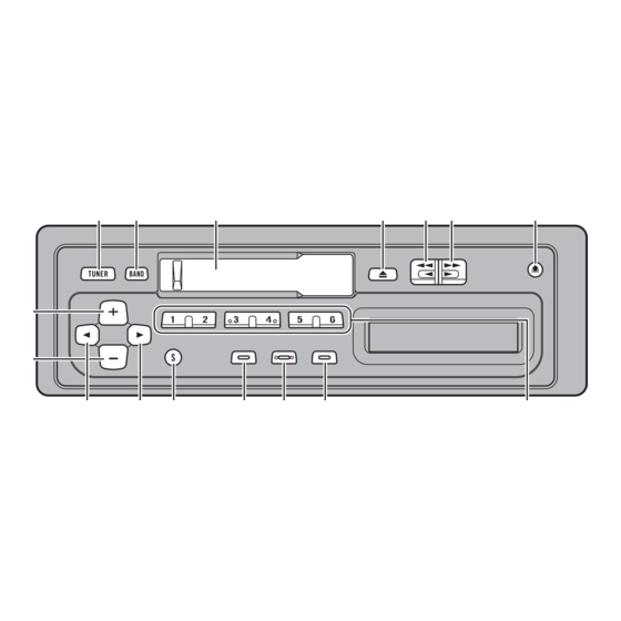
KEH-1900
This product conforms to CEMA cord colors.
Le code de couleur des câbles utilisé pour ce produit est
conforme à CEMA.
Los colores de los cables este producto se conforman
con el código de colores CEMA.
Printed in
Imprimé
<CRD3100-A/JS> UC
<99H00F0P01>
Connecting the Units
Note:
•
This unit is for vehicles with a 12-volt battery
•
When this product's source is switched ON, a
and negative grounding. Before installing it in a
control signal is output through the blue/white
recreational vehicle, truck or bus, check the bat-
lead. Connect to an external power amp's system
tery voltage.
remote control or the car's Auto-antenna relay
•
To avoid shorts in the electrical system, be sure
control terminal. (Max. 300 mA 12 V DC.) If the
to disconnect the ≠ battery cable before begin-
car features a glass antenna, connect to the anten-
ning installation.
na booster power supply terminal.
•
Refer to the owner's manual for details on con-
•
When an external power amp is being used with
necting the power amp and other units, then
this system, be sure not to connect the blue/white
make connections correctly.
lead to the amp's power terminal. Likewise, do
not connect the blue/white lead to the power ter-
•
Secure the wiring with cable clamps or adhesive
minal of the auto-antenna. Such connection could
tape. To protect the wiring, wrap adhesive tape
cause excessive current drain and malfunction.
around them where they lie against metal parts.
•
To avoid short-circuiting, cover the disconnected
•
Route and secure all wiring so it cannot touch
lead with insulating tape. Especially, insulate the
any moving parts, such as the gear shift, hand-
unused speaker leads without fail. There is a pos-
brake and seat rails. Do not route wiring in
sibility of short-circuiting if the leads are not
places that get hot, such as near the heater outlet.
insulated.
If the insulation of the wiring melts or gets torn,
•
If this unit is installed in a vehicle that does not
there is a danger of the wiring short-circuiting to
have an ACC (accessory) position on the ignition
the vehicle body.
switch, the red lead of the unit should be con-
•
Don't pass the yellow lead through a hole into
nected to a terminal coupled with ignition switch
the engine compartment to connect to the battery.
ON/OFF operations. If this is not done, the vehi-
This will damage the lead insulation and cause a
cle battery may be drained when you are away
very dangerous short.
from the vehicle for several hours.
•
Do not shorten any leads. If you do, the protec-
tion circuit may fail to work when it should.
•
Never feed power to other equipment by cutting
the insulation of the power supply lead of the
unit and tapping into the lead. The current capac-
ity of the lead will be exceeded, causing over-
heating.
•
When replacing fuse, be sure to use only fuse of
the rating prescribed on this unit.
ACC position
No ACC position
•
Since a unique BPTL circuit is employed, never
wire so the speaker leads are directly grounded or
•
The black lead is ground. Please ground this lead
the left and right ≠ speaker leads are common.
separately from the ground of high-current prod-
•
Speakers connected to this unit must be high-
ucts such as power amps.
power types with minimum rating of 40 W and
If you ground the products together and the
impedance of 4 to 8 ohms. Connecting speakers
ground becomes detached, there is a risk of dam-
with output and/or impedance values other than
age to the products or fire.
those noted here may result in the speakers catch-
ing fire, emitting smoke or becoming damaged.
•
Cords for this product and those for other prod-
ucts may be different colors even if they have the
same function. When connecting this product to
another product, refer to the supplied Installation
manuals of both products and connect cords that
have the same function.
This Product
Rear output
Fuse
Antenna jack
Black (ground)
To vehicle (metal) body.
Red
To electric terminal controlled by ignition
switch (12 V DC) ON/OFF.
Yellow
To terminal always supplied with power
regardless of ignition switch position.
With a 2 speaker system,
connect to the 2 speakers
in the front or the rear.
Perform these connections
when using a different amp
(sold separately).
Connecting cords with
RCA pin plugs
(sold separately)
To system control terminal
of the power amp or Auto-antenna
relay control terminal.
(Max. 300 mA 12 V DC.)
System remote
Blue/white
control
Left speaker
Right speaker
+
White
Gray
+
Front
Front
White/black
Gray/black
≠
≠
Green
Violet
+
+
Rear
Rear
Green/black
Violet/black
≠
≠
+
+
Rear
Rear
≠
≠
<ENGLISH>
Power amp
(sold separately)
Advertisement
Table of Contents

Related Manuals for Pioneer KEH-1900


Summary of Contents for Pioneer KEH-1900
- Page 1 Fuse make connections correctly. lead to the amp’s power terminal. Likewise, do To system control terminal KEH-1900 Antenna jack of the power amp or Auto-antenna not connect the blue/white lead to the power ter- •...
- Page 2 Connexion des appareils < FRANÇAIS > Remarque: • Cet appareil est destiné aux véhicules avec une • Quand la source de ce produit est positionnée sur batterie de 12 V, avec pôle négatif à la masse. ON, un signal de commande est sorti par le fil Avant de l’installer dans un véhicule de loisir, un bleu/blanc.
- Page 3 <ESPAÑOL> Conexión de las unidades Nota: • Cuando se conecta la fuente de este producto, una • Esta unidad es para vehículos con batería de 12 señal de control se emite a través del conductor voltios y con conexión a tierra. Antes de instalar azul/blanco.
- Page 4 <ENGLISH> Installation Note: DIN Front-mount DIN Rear-mount • Before finally installing the unit, connect the wiring temporarily, making sure it is all connect- ed up properly, and the unit and the system work 7 Installation with the rubber bush 7 Removing the Unit 7 Installation using the screw holes on properly.
- Page 5 < FRANÇAIS > Installation Remarque: Montage avant DIN Montage arrière DIN • Avant de finaliser l’installation de l’appareil, con- necter temporairement le câblage en s’assurant que tout est correctement connecté et que 7 Installation avec une bague en 7 Dépose de l’únite 7 Installation en utilisant les trous de vis l’appareil et le système fonctionnement correcte- ment.
- Page 6 Instalación <ESPAÑOL> Nota: Montaje delantero DIN Montaje trasero DIN • Antes de finalmente instalar la unidad, conecte el cableado temporalmente y asegúrese de que todo esté conectado correctamente y que la unidad y 7 Instalación con tope de goma 7 Quitado de la unidad 7 Instalación usando los agujeros para el sistema funcionan debidamente.
Need help?
Do you have a question about the KEH-1900 and is the answer not in the manual?
Questions and answers