Table of Contents
Advertisement
S/M NO.: WF42200100
DAEWOO ELECTRONICS CO., LTD.
612-1, AHYEON-DONG, MAPO-GU,
SEOUL, KOREA.
C.P.O. BOX 8003 SEOUL KOREA
TELEX: DWELEC K28177-8
CABLE:"DAEWOOELEC"
FAX: (02) 364-5588/5305
TEL: (02) 360/7315~7
PRINTED DATE: APR. 1996
Service Manual
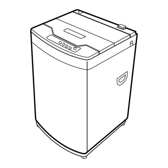
Full-Auto Electric Washing Machine
DWF-4220 (Series)
DWF-5020 (Series)
DAEWOO ELECTRONICS CO., LTD.
Advertisement
Table of Contents


Need help?
Do you have a question about the DWF-4220 Series and is the answer not in the manual?
Questions and answers