Table of Contents
Advertisement
Quick Links
Advertisement
Table of Contents

Related Manuals for SitePro 26-DT05


Summary of Contents for SitePro 26-DT05
- Page 2 Precaution 1. Avoid heavy shock For long-distance transportation, pay attention to external package and shock proof. 2. Setting and moving When placing the instrument on the tripod head, hold the instrument and rotate the tripod screw until it is fixed securely on top of the tripod head.
- Page 3 Catalogue 1. Nomenclature 2. Display and display mark 3. Operating keyboard and operating key 4. Preparative before measurement 4.1 Leveling the instruement. 4.2 Power switch on 4.3 Battery power display 4.4 Charge the battery 5. Angle measurement 5.1 Measuring a HA and vertical angle 5.2 Switch horizontal angle HA / HA 5.3 Setting a horizontal angle 5.4 Repetition angle measurement...
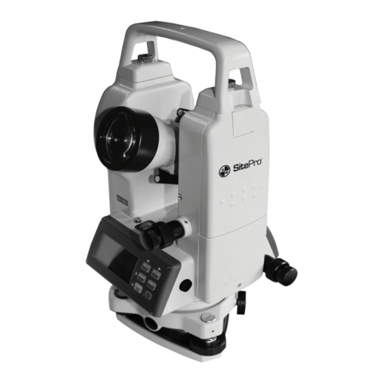
- Page 4 1. Nomenclature...
- Page 5 1. carrying handle 2. handle screw 3. sighting collimator 4. vertical tangent screw and motion clamp 5. operating key 6. RS-232C communication interface 7. object lens 8. plate level 9. display window 10. eyepiece 11. base plate 12. foot screw 13.
- Page 6 3. Operating keyboard and operating key DIST S/H/V OSET HOLD V / % Keys Function 1 Function 2 OSET set horizontal angle 0 distance measurement repeat measurement hold the horizontal HOLD horizontal angle angle select the second turn on or off function illumination switch horizontal...
- Page 7 4.1.1. Place the tripod First, put the tripod leg in the proper position and tighten the locking screws. 4.1.2. Attaching the instrument to the tripod head Place the instrument carefully on the tripod head, and move the instrument slowly by loosening adjusting screw. Align the plumb bob with the point on the ground when aligned, tighten the adjusting screw.
- Page 8 c. Repeat the above procedure for each 90 revolution of the instrument and check whether the level bubble is correctly centered for all points. 4.1.5. Centering the instrument with optical plummet Adjust the eyepiece of the optical plummet telescope to the user’s eyesight.
- Page 9 Note: a. In order to make sure instrument work continuously, pay attention to battery power display. if battery power is insufficient, replace battery. please see 4.3 Battery power display. b. For setting the vertical angle at 0, a datum 0 is provided on the vertical angle scale circumference.
- Page 10 5. Angle measurement 5.1 Measuring a HA and vertical angle operating display 1 . Collimate the first target. 2 . Press 0SET 【 】 11-03-20 15:48 twice, and set ° ′ ″ horizontal angle of target A ° ′ ″ 0 °...
- Page 11 5.2 Switching horizontal angle HA /HA operating display 11-03-20 15:48 1. Collimate the target 90 ° 00 ′ 00 ″ 0 ° 10 ′ 01 ″ 2. Press R /L 【 】 , 11-03-20 15:48 the mode horizontal ° ′ ″...
- Page 12 5.4 Repetition angle measurement To find the horizontal angle with greater precision, perform repetition measurement. operating display 11-03-20 15:48 1. Press 【SFT】 ,and then press 【 H O LD 】 N - 0 to begin repetition ° ″ ′ angle measurement. RE P 2.
- Page 13 6. Recollimate the first target A using the horizontal tangent screw and motion clamp. 11-03-20 15:48 7. Press OSET 】 , and 【 make the horizontal N - 1 angle of A is ′ ° 00 ″ ′ ° ″ RE P 8.
- Page 14 5.5 Measuring a percent of grade(slope measurement) operating display 11-03-20 15:48 1. Press 【V %】 , display of vertical - 3.108 % angle switches to percent grade. ° ′ ″ 11-03-20 15:48 again. 【 V %】 2. Press The display turns °...
- Page 15 6.1 RS-232 serial communication interface The series instrument has RS-232 interface joined with the computer or PDA through the cable. The measurement data can be transferred to the computer or the data collection equip -ment. Remember the interface is under the vertical knob. 6.2 Recording measurement data In the different measuring mode, press , and then press...
- Page 16 operating display 1. Press power on, 【 】 , 11-03-20 15:48 come in the memory mode. The first line display the ---------------- effective data items in the memory. 2. Press the second , 【 】 11-03-20 15:48 line will glint, and the instru -ment output the data to the interface, until it finish ----------------...
- Page 17 4. Minium angle display: 1’ , 5’’, 10’’. 5. Setting communication baud rate: 1200, 2400, 4800, 9600. 6. Selecting data recording method: interface memory (OFF), (ON). 7. Collimation error correction: OFF, ON. 8. Selecting angle unit: dms , gon (OFF) (ON) 8.2 Function setting method In the setting mode, the keys are assigned function as following:...
- Page 18 8.3 Time setting operating display 1. Press , and S F T 【 】 11-03-20 15:48 then press L /R 【 】 come in the setting mode. 2. Press HOLD 【 】to 11-03-20 15:48 select the item (month,data, year, hour,minute,second), ·...
- Page 19 can measure and adjust tilt compensator 0 position error. and you can measure collimation error in your instrument so that the instrument can correct subsequent single face observations. The 0 index of the vertical circle of your instrument can be also reset, and the index error that will affect the accuracy of vertical angle measurement can be corrected.
- Page 20 10. Other function 10.1 Measuring distance Measuring distance with the cross-hair in telescope reticle is another application of the theodolite series products. This is a simple method, but scale station pole is needed, for example, horizontal measuring staff and apparent distance staff. By view -ing through the telescope, the length between upper and lower stadia hairs multiplied by 100 is the distance from the instrument to the station pole(the length refers to the reading from station...
- Page 21 The vertical axis is inclined in “X” vertical axis Note: The angle display is unstable when instrument is on an un -stable stage or a windy day. You should turn off the auto tilt compensation. Turn on or off auto tilt compensation function, please refer ...
- Page 22 b. Carry out the adjustment in the order listed, as the adjust -ment are dependent one upon another. Adjustments carried out in the wrong sequence may even nullify previous adjustments. c. Conclude adjustments by tightening the adjustment screws securely (but do not tightening them more than necessary, as you may strip the threads, twist off the screw or place undue stress on the parts).
- Page 23 b. Correct the remaining 1/2 amount of the bubble displacement with the leveling screws. c. Revolve the instrument 180 or 200g around the vertical axis once more and check bubble movement if the bubble is still displaced, then repeat the adjustment. adjustment screw tribrach bubble...
- Page 24 Check a. Set the instrument on the tripod and level it carefully. b. Sight the cross-hair on a well-defined point A on the wall at a distance of at least 50 meters(160ft). c. Next swing the telescope and check whether the point travels along the length of the vertical cross hair.
- Page 25 a. Unscrew the cross-hair adjustment section cover by revolv -ing it in the counter-clockwise direction. this will expose four eyepiece section attachment screws. b. Loosen all four attachment screws slightly with the accessory screw-driver(while taking note of the number of the revolutions). Make vertical cross-hair coincide with A by turning eyepiece and tighten the four attachment screws.
- Page 26 f. Loosen the vertical motion clamp and tangent screw and plunge the instrument 180° or 200gon and fix a sight on point C, which should coincide with the previous point B. reticle adjustment screw Adjustment a. Unscrew the cover of cross-hair adjusment section. b.
- Page 27 11.5 Check and adjust optical plummet optical Adjustment is required to make the line of sight of plummet telescope coincide with the vertical axis (as otherwise the vertical axis will not be in the true vertical when the instru -ment is optically plumbed.) Check a.
- Page 28 b. Revolve the instrument 180 or 200g around the vertical axis, and check the center mark. If it is coincided to the point, then further adjustment is not required. Otherwise, repeat the adjustment. Note: To move center mark, loosen adjustment screw on one side and tighten adjustment screw on the other side according to the loosened number.
- Page 29 13. Error displays Vertical angle 0 position is out of range or set with incorrect procedure. Tilt angle compensator 0 positon is out of range or set with incorrect procedure. During measuring of the collimation error, the measured value measured is out of range. There’s abnormality in internal memory system.
- Page 30 Absolutely Method encoding Electronic angle 1 ″/ 5 ″ /10 ″ Minimum reading measurement 2 ″ Accuracy Diameter of circle 71mm Illuminator Reticle plate EDM interface communitcation Data export interface Vertical angle Electric incline sensor Tilt compensation compensation arrange ± 3 ′ Minimum reading 1 ″...
Need help?
Do you have a question about the 26-DT05 and is the answer not in the manual?
Questions and answers