Table of Contents
Advertisement
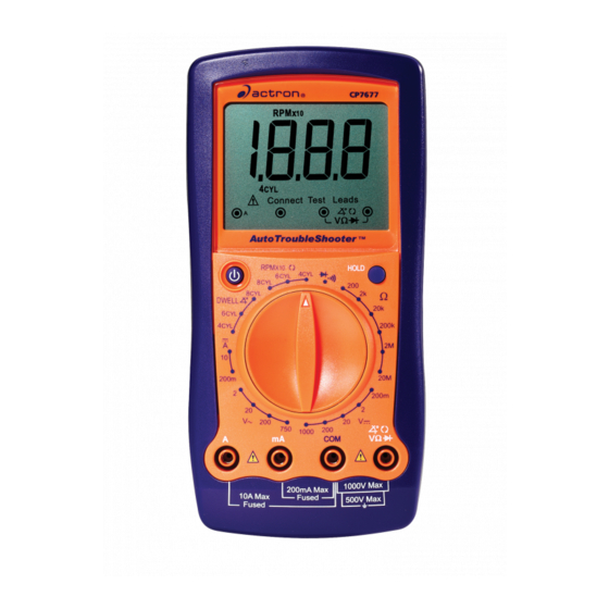
Auto TroubleShooter
OPERATING
INSTRUCTIONS
Index
Safety Precautions ......................................... 2
Vehicle Service Information ........................... 3
Visual Inspection ............................................ 3
Electrical Specifications ............................... 34
Warranty ..................................................... 104
Functions and Display Definitions ............ 4
Setting the Range ..................................... 6
Battery and Fuse Replacement ................ 7
Measuring DC Voltage .............................. 8
Measuring AC Voltage .............................. 8
Measuring Resistance .............................. 9
Measuring DC Current .............................. 9
Testing for Continuity .............................. 10
Testing Diodes ........................................ 11
Measuring Engine RPM .......................... 11
Measuring Dwell ..................................... 12
2. Automotive Testing with the CP7677
General Testing ...................................... 13
- Testing Fuses ...................................... 13
- Testing Switches ................................. 13
- Testing Solenoids and Relays ............ 14
Starting / Charging System Testing ....... 15
- No Load Battery Test .......................... 15
- Engine Off Battery Current Draw ........ 15
™
- Voltage Drops ...................................... 17
- Charging System Voltage Test ........... 18
Ignition System Testing .......................... 19
- Ignition Coil Testing ............................. 19
- Ignition System Wires .......................... 21
- Hall Effect Sensors/Switches .............. 22
- Magnetic Pick-Up Coils ....................... 23
- Reluctance Sensors ............................ 23
- Ignition Coil Switching Action .............. 24
Fuel System Testing ............................... 25
Solenoid Dwell .................................... 25
Testing Engine Sensors .......................... 27
- Oxygen (O
- Temperature Type Sensors ................ 29
Throttle and EGR Valve Position,
Vane Air Flow ...................................... 30
- Mass Air Flow (MAF) Sensors ............ 32
Instrucciones en español ....35
Instructions en français .......69
1
CP7677
2
Advertisement
Table of Contents

Subscribe to Our Youtube Channel
Related Manuals for Actron CP7677


Summary of Contents for Actron CP7677
-
Page 1: Table Of Contents
Measuring Dwell ........12 Vane Air Flow ........30 - Manifold Absolute Pressure (MAP) and Barometric Pressure (BARO) Sensors 31 2. Automotive Testing with the CP7677 - Mass Air Flow (MAF) Sensors .... 32 General Testing ........13 - Testing Fuses ........13 - Testing Switches ......... -
Page 2: Safety Precautions
Actron Manufacturing Co. or anyone connected with it for loss or damages suffered through reliance on any information contained in this manual or misuse of accompanying product. Actron Manufacturing Co. -
Page 3: Vehicle Service Information
Vehicle Service Manual – Sources For Service Information The following is a list of sources to obtain vehicle service information for your specific vehicle. • Contact your local Automotive Dealership Parts Department. • Contact local retail auto parts stores for aftermarket vehicle service information. •... -
Page 4: Multimeter Basic Functions
Section 1. Multimeter Basic Functions Digital multimeters or DMMs have many special features and functions. This section defines these features and functions, and explains how to use these functions to make various measurements. Alligator Clip Adapters Some multimeter tests and measurements are more easily done using alligator clips instead of test prods. -
Page 5: Functions And Display Definitions
Functions and Display Definitions 1. ROTARY SWITCH 8. DC AMPS Switch is rotated to select a function. This function is used for measuring DC (Direct Current) Amps in the range of 0 2. DC VOLTS to 10A. This function is used for measuring DC 9. -
Page 6: Setting The Range
Setting the Range Now assume we set the multimeter to the 2V range. (See Fig. 2) Two of the most commonly asked ques- tions about digital multimeters are What The multimeter display now shows a “1” does Range mean? and How do I know and nothing else. -
Page 7: Battery And Fuse Replacement
the accuracy of the measurement by ei- Fig. 4 ther increasing or decreasing the number of digits after the decimal point. Battery and Fuse Replacement Important: A 9 Volt battery must be in- stalled before using the digital multim- eter. (see procedure below for installa- tion) Battery Replacement value... -
Page 8: Measuring Dc Voltage
Measuring DC Voltage 6. View reading on display - Note range setting for correct units. This multimeter can be used to measure NOTE: 200mV = 0.2V DC voltages in the range from 0 to 1000V. You can use this multimeter to do any DC voltage measurement called out in the vehicle service manual. -
Page 9: Measuring Resistance
Measuring Resistance ments, polarity is not important. The test leads just have to be connected Resistance is measured in electrical across the component. units called ohms (Ω). The digital multi- 6. Turn multimeter rotary switch to meter can measure resistance from 0.1Ω desired OHM range. -
Page 10: Testing For Continuity
Testing for Continuity Fig. 10 Electrical Continuity is a quick way to do a resis- Device tance test to determine if a circuit is open or closed. The multimeter will beep when the circuit is closed or shorted, so Voltage you don’t have to look at the display. -
Page 11: Testing Diodes
Testing Diodes 7. Switch RED and BLACK test leads and repeat Step 6. A diode is an electrical component that 8. Test Results allows current to only flow in one direc- tion. When a positive voltage, generally If the display showed: greater than 0.7V, is applied to the an- •... -
Page 12: Measuring Dwell
connect RED test lead to negative side of primary ignition coil. (refer to vehicle service manual for loca- tion of ignition coil) 4. Connect BLACK test lead to a good vehicle ground. 5. Turn multimeter rotary switch to correct CYLINDER selection. 6. -
Page 13: General Testing
Section 2. Automotive Testing • If you hear tone - Fuse is good. The digital multimeter is a very useful tool for trouble-shooting automotive elec- • If you don’t hear tone - Fuse is trical systems. This section describes blown and needs to be replaced. how to use the digital multimeter to test NOTE: Always replace blown fuses the starting and charging system, igni-... -
Page 14: Testing Solenoids And Relays
• If you hear tone - The switch is closed. • If you don’t hear tone - The switch is open. 8. Repeat Step 7 to verify switch op- eration. Good Switch: Tone turns ON and OFF as you operate switch. Bad Switch: Tone always ON or tone always OFF as you operate switch. -
Page 15: Starting/Charging System Testing
Starting/Charging System Testing The starting system “turns over” the engine. It consists of the battery, starter motor, starter solenoid and/or relay, and associated wiring and connections. The charging system keeps the battery charged when the engine is running. This system consists of the alternator, voltage regulator, battery, and associated wiring and connections. -
Page 16: Cranking Voltage/Battery Load Test
4. Disconnect positive (+) battery Fig. 21 cable. 5. Connect RED test lead to positive (+) battery terminal. 6. Connect BLACK test lead to posi- tive (+) battery cable. Black NOTE: Do not start vehicle during this test, because multimeter damage may result. -
Page 17: Voltage Drops
Voltage Drops If multimeter overranges, turn multim- This test measures the voltage drop across eter rotary switch to the 2V DC range. wires, switches, cables, solenoids, and (See Setting the Range on page 6) connections. With this test you can find excessive resistance in the starter sys- 6. -
Page 18: Charging System Voltage Test
Charging System Voltage Test 8. Open throttle and Hold engine This test checks the charging system to speed (RPM) between 1800 and see if it charges the battery and pro- 2800 RPM. vides power to the rest of the vehicles electrical systems (lights, fan, radio etc). -
Page 19: Ignition System Testing
Ignition System Testing The ignition system is responsible for providing the spark that ignites the fuel in the cylinder. Ignition system components that the digital multimeter can test are the primary and secondary ignition coil resistance, spark plug wire resistance, hall effect switches/sensors, reluctance pick-up coil sensors, and the switching action of the primary ignition coil. - Page 20 12. Move RED test lead to secondary ignition coil terminal. • Refer to vehicle service manual for location of secondary ignition coil terminal. • Verify BLACK test lead is con- nected to primary ignition coil nega- tive (-) terminal. 13. View reading on display. 14.
-
Page 21: Ignition System Wires
Ignition System Wires This test measures the resistance Fig. 26 of spark plug and coil tower wires while they are being flexed. This Black test can be used for distributorless ignition systems (DIS) provided the system does not mount the ignition coil directly on the spark plug. -
Page 22: Hall Effect Sensors/Switches
Hall Effect Sensors/Switches Hall Effect sensors are used whenever 4. Insert test lead into the vehicle computer needs to know test lead jack. speed and position of a rotating object. 5. Connect RED test lead to sensor Hall Effect sensors are commonly used SIGNAL pin. -
Page 23: Magnetic Pick-Up Coils
Magnetic Pick-Up Coils – Reluctance Sensors Reluctance sensors are used whenever 3. Connect RED test lead to either the vehicle computer needs to know sensor pin. speed and position of a rotating object. 4. Connect BLACK test lead to re- Reluctance sensors are commonly used maining sensor pin. -
Page 24: Ignition Coil Switching Action
Ignition Coil Switching Action vehicle service manual for location This test checks to see if the negative of this wire) terminal of the primary ignition coil is getting switched ON and OFF via the • For all vehicles with distributors, ignition module and camshaft / crank- connect RED test lead to negative shaft position sensors. -
Page 25: Fuel System Testing
Fuel System Testing Typical Mixture Control Solenoid Connection The requirements for lower vehicle emissions has increased the need for more precise engine fuel control. Auto manufacturers began using electronically controlled carburetors in 1980 to meet emission requirements. Today’s modern vehicles use electronic fuel injection to precisely control fuel and further lower emissions. -
Page 26: Measuring Fuel Injector Resistance
Measuring Fuel Injector Resistance Fuel injectors are similar to solenoids. 5. Connect RED and BLACK test They contain a coil that is switched ON leads across fuel injector pins. and OFF by the vehicle computer. This Make sure you connect test leads test measures the resistance of this coil across fuel injector and not the wir- to make sure it is not an open circuit. -
Page 27: Testing Engine Sensors
Testing Engine Sensors In the early 1980’s, computer controls were installed in vehicles to meet Federal Government regulations for lower emissions and better fuel economy. To do its job, a computer-controlled engine uses electronic sensors to find out what is happening in the engine. - Page 28 • Connect BLACK test lead to re- • Multimeter display should read... maining heater pin. – 0.6V or greater for Zirconia Type • Turn multimeter rotary switch to Sensors. 200Ω range. – an Ohmic(Resistance) value for • View reading on display. Titania Type Sensors.
-
Page 29: Temperature Type Sensors
Temperature Type Sensors A temperature sensor is a thermistor or 9. View and record reading on dis- a resistor whose resistance changes with play. temperature. The hotter the sensor gets, 10. Disconnect multimeter test leads the lower the resistance becomes. Typi- from sensor and reconnect sen- cal thermistor applications are engine sor wiring. -
Page 30: Position Type Sensors
Position Type Sensors • If multimeter overranges on larg- Position sensors are potentiometers or est range, then sensor is an open a type of variable resistor. They are circuit and is defective. used by the computer to determine po- sition and direction of movement of a 7. -
Page 31: Manifold Absolute Pressure (Map) And Barometric Pressure (Baro) Sensors
• To test intake air tempera- Fig. 34 ture sensor see Temperature Type Sensors on page 29. Frequency EGR Valve Position Only • Remove vacuum hose from EGR valve. Ground • Connect hand vacuum pump Only to EGR valve. • Gradually apply vacuum to slowly open valve. -
Page 32: Mass Air Flow (Maf) Sensors
The CP7677 can only test the dc • Remember to multiply display voltage and low frequency type of reading by 10 to get actual RPM. - Page 33 8. Operate Sensor. Fig. 35 • Start engine and let idle. • Display reading should... Frequency Only - increase in voltage from Key On Engine OFF for DC type MAF sensors. Ground Only - increase in RPM from Key On Engine OFF for Low Fre- quency type MAF sensors.
-
Page 34: Electrical Specifications
Electrical Specifications DC Volts Range: 200mV, 2V, 20V, 200V Accuracy : ± (0.5% rdg + 5 dgts) Range: 1000V Accuracy: ±(0.8% rdg + 5 dgts) AC Volts Range: 2V, 20V, 200V Accuracy : ± (0.8% rdg + 5 dgts) Range: 750V Accuracy: ±(1.0% rdg + 4 dgts) DC Current Range: 200mA...
Need help?
Do you have a question about the CP7677 and is the answer not in the manual?
Questions and answers
Do you sell extra leads. One got burned and is not working