Advertisement
Advertisement
Table of Contents

Subscribe to Our Youtube Channel
Related Manuals for Craig CHT915


Summary of Contents for Craig CHT915
- Page 1 Model: CHT915...
- Page 2 This unit has a long cord that can easily be tripped on or pulled on, causing injury,Please make sure...
-
Page 4: Power Source
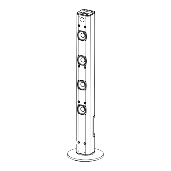
POWER SOURCE Insert the small plug from supplied AC/DC adaptor to DC IN jack on the rear of the unit and insert the AC/DC adaptor to the wall outlet having AC 100-240~;50/60 Hz. AC/DC adapter NOTE:This AC/DC adapter is intended to be correctly operated in a vented indoor wall outlet. - Page 5 Placing on Floor in Vertical (Continued): Speaker Net Remote Sensor Speakers The Speaker Net can be take out and reassembled as the figure above.
- Page 6 Placing on Table in Horizontal To place the unit on a flat surface such like table, insert the 2 (two) supplied Plastic Brackets into the small slot of the holder on the rear of unit as the Fig.1 below. Small Slot Fig.1 Fig.2 Insert the 2 (Two) supplied Plastic Stands into the inner small slot as the Fig.
-
Page 7: Wall Mount
Wall Mount 1. Wall mount the unit to the wooden wall A : Mounted the 2 (Two) supplied Metallic Brackets on the wooden wall by the 4 (Four) supplied screws as the Fig.1 below: Fig.1 supplied bracket supplied screws supplied bracket supplied screws B : Put the sound bar onto the Metallic Brackets as Fig.2 below. - Page 8 INSTALLATION Wall Mount (Continued): 2. Mount on Wall A.Mark the position of the mounting holes on the wall using a pencil. B.Drill appropriate holes by powerful electric drill on wall. C.Insert the supplied plastic inserts into the holes by hammer. D.Mounted the supplied Metallic Brackets to the holes with supplied screws.
-
Page 9: Location Of Controls
LOCATION OF CONTROLS MAIN UNIT POWER button 1. INDICATOR / TUNE+ button 2. AUX IN 2 jack (Play/Pause) button 3. SOURCE button / TUNE- button 4. VOL- (Volume Down) button 11. FM Antenna 5. EQ (Equalizer) button 12. AUX IN 1 jacks 6. - Page 10 LOCATION OF CONTROLS REMOTE CONTROL POWER SOURCE TUNE+ TUNE- POWER button (Mute) button / TUNE - button / TUNE+ button (Play/Pause) button 3. VOL (Volume)+/- buttons 8. EQ (Equalizer) button 4. SOURCE button...
-
Page 11: Battery Installation--- Remote Control
BATTERY INSTALLATION--- REMOTE CONTROL -First Time Use Remove and discard the insulation tab as figure on the right -Replacing Batteries For Remote Control 1. Push and slide out the battery holder as figure 1 below. 2. Replace the battery with a new CR2025 button cell as the polarity markings on the rear of the Remote Control. -
Page 12: General Operations
GENERAL OPERATIONS 1. Connect the AC/DC adapter to the unit and wall outlet as the previous procedure . The red indicator will light. 2. Press the Power button on the unit or remote control to power on the unit from standby mode. 3. -
Page 13: Listen To Fm Radio
LISTEN TO FM RADIO 1. Power ON the unit as previous procedures. 2. Press the SOURCE button repeatedly until the color of the indicator changed to Green. 3. Press and hold the /TUNE - or /TUNE + buttons until the indicator starts blinking. The unit will start to search next (or previous) available FM radio station then plays. - Page 14 AUX IN 1 : LISTEN TO TV/DVD/VCR/DVR White Audio out jacks on TV/DVD/ VCR/DVR AUX IN 1 (RCA cable included) 1. Connect one end of RCA audio connection cable (supplied) to the AUX IN 1 jacks on the rear of the unit as the figure above. 2.
- Page 15 AUX IN 2 : LISTEN TO EXTERNAL AUDIO DEVICES INDICATOR AUX IN 2 SOURCE VOL- VOL+ POWER TUNE- TUNE+ 1. Connect one end of supplied audio connection cable to the AUX IN 2 jack on the top of the unit as the figure above.
-
Page 16: Troubleshooting Guide
TROUBLESHOOTING GUIDE Check the followings before requesting service SYMPTOM POSSIBLE CAUSE POSSIBLE SOULTION Power AC/DC adapter Connect the power AC/DC adapter not connected No power The unit is in Standby mode Press button to turn on the unit Raise volume level by pressing the VOL Volume in minimum position (Volume) + button Play the music/movie in the connected... -
Page 17: General Specifications
GENERAL SPECIFICATIONS Power Source..................DC 16V; 1.8A. Radio Coverage....................FM 87.5 -108.0 MHz Impedance of Speakers: Loud Speakers ....................... 8 Ohm, 15W x 2 Tweeters........................8 Ohm, 5W x 2 Bluetooth Effective Range in Open Aera..............Up to 32 feet Remote Effective Range.....................Up to 15 feet Accessories 1 x AC/DC Adaptor ( Input: AC 100-240V~ ;...
Need help?
Do you have a question about the CHT915 and is the answer not in the manual?
Questions and answers