Table of Contents
Advertisement
Quick Links
Advertisement
Table of Contents
Troubleshooting

Related Manuals for Onset hobo u30

Summary of Contents for Onset hobo u30
- Page 2 Onset Computer Corp Contacting Onset For support, please contact the company that you bought the products from: Onset Computer Corporation or an Onset Authorized Dealer. Onset Computer Corporation 470 MacArthur Blvd. Bourne, MA 02532 Mailing Address: P.O. Box 3450 Pocasset, MA 02559-3450...
-
Page 3: Table Of Contents
Initial HOBOlink Setup ..........................11 Initial Hardware Setup ........................... 12 Connecting the HOBO U30 Station to HOBOware Pro ............... 13 Configuring Analog Sensor Ports or a TRMSA Module .............. 14 Changing the State of the U30 Relay Contact ................16 Basic Hardware Setup .......................... - Page 4 Removing/Replacing a Sensor ......................52 Testing Smart Sensors ..........................52 Checking the U30 Status ........................52 Inspecting the HOBO U30 Station ...................... 53 Troubleshooting the HOBO U30 Station ..................54 The Smart Sensor Expander Board ........... 56 Opening the Secondary Cable Slot ..................... 56 Installing the Expander Board ......................
- Page 5 Onset Computer Corp Memory ................................. 75 Connection Status LEDs ......................... 76 Logger Status LEDs ........................... 78 Items Required for Field Installation ....................79 Accessories ..............................80 FCC Part 15 Compliance ......................... 81 Wi-Fi Compliance ............................82 Ethernet Compliance ..........................83 Tripod Setup ..................
-
Page 6: About The Hobo U30 Station
The HOBO U30 Station is a data logging system that can be easily reconfigured and adapted to a wide variety of applications. Up to 15 channels of data can be recorded and monitored with HOBOware Pro software. -
Page 7: Key Features
Rechargeable Battery The HOBO U30 Station uses a Sealed Lead Acid battery that can be recharged via a solar panel or AC adapter. This provides continuous power to keep the HOBO U30 Station recording and transmitting data for years. -
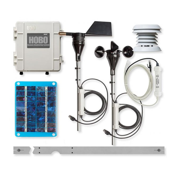
Page 8: U30 Station Components
Onset Computer Corp U 3 0 S t a t i o n C o m p o n e n t s This topic describes the components for the HOBO U30 Station. Some components apply to specific models only, as noted. - Page 9 15. Internal Enclosure - provides a second weather-proof housing for the electronics in the HOBO U30 Station. You should never open this case. Doing so will void the warranty. 16. Status LEDs There are three Light Emitting Diode (LED) status indicators.
-
Page 10: Software
Onset Computer Corp S o f t w a r e The HOBO U30/RC Station is designed primarily for use with HOBOlink, which allows for continuous logging and transmission of data using remote communication technology. There is some configuration however that requires HOBOware Pro software. Before you set up your system, it is important to understand when to use HOBOlink and HOBOware Pro. -
Page 11: Smart Sensors
Refer to www.onsetcomp.com for a current list of available sensors. Cable Length The HOBO U30 Station can work with a maximum total of Smart Sensor cable lengths up to 100 meters (328 feet), as measured from the logger connection point to the electronics embedded in the individual cables. -
Page 12: The Analog Sensor Port
Configuration options include scaling parameters, and excitation power. See page 14, as well as the HOBOware User’s Manual for configuration details. If your HOBO U30 Station does not have an Analog Sensor Port and you wish to upgrade to one, contact Onset Computer Corporation for information. - Page 13 Onset Computer Corp • Continuous mode The logger supplies constant excitation power to the sensor for the entire duration of the deployment. This mode will result in reduced battery life. Continuous mode is required if the sensor needs more than two minutes of warm-up time. The Analog Sensor Port begins functioning when logging begins.
-
Page 14: Setup And Test
Onset Computer Corp S E T U P A N D T E S T C o n f i g u r a t i o n S u m m a r i e s This topic summarizes different paths you should take for HOBOlink and hardware configuration depending on your U30 Station model and optional configuration you may need to perform. - Page 15 Onset Computer Corp U30/Wi-Fi with DHCP and Analog Sensors Initial HOBOlink Setup (page 11) Basic Hardware Setup (page 17), Steps 1-3 Configuring Network Setup (page 24), Steps 1-3 Configuring Analog Sensor Ports or TRSMA Module (page 14), Steps 3-5 Basic Hardware Setup (page 17), Step 4...
-
Page 16: Initial Hobolink Setup
Onset Computer Corp I n i t i a l H O B O l i n k S e t u p Before you connect the battery to the U30 Station, you should perform this procedure to setup your HOBOlink account and perform initial configuration and testing for the U30. -
Page 17: Initial Hardware Setup
Onset Computer Corp I n i t i a l H a r d w a r e S e t u p Before you take the U30 Station into the field for deployment you should perform the following preliminary hardware assembly and configuration: •... -
Page 18: Connecting The Hobo U30 Station To Hoboware Pro
1. Connect to a computer. To connect to a computer running HOBOware Pro, plug the “mini-USB” end of the USB cable provided into the USB port on the HOBO U30 Station and connect the “A” end to the USB port in your computer. -
Page 19: Configuring Analog Sensor Ports Or A Trmsa Module
Onset Computer Corp C o n f i g u r i n g A n a l o g S e n s o r P o r t s o r a T R M S A M o d u l e This is a branch of the Basic Hardware Setup procedure (page 17) for those who need to configure Analog Sensor Ports or a TRMSA Module. - Page 20 Onset Computer Corp 11. Disconnect the battery from the U30 Station and then reconnect it to cycle power. The U30 Station will connect to HOBOlink at the next Connection Interval. Proceed to Final HOBOlink Setup and Test (page 18).
-
Page 21: Changing The State Of The U30 Relay Contact
5. To test the relay, click the Close Relay or Open Relay button (button that appears depends on which state the relay is in). You should hear a click in the HOBO U30 Station. Click the button again to return to the default state. Use a digital multimeter to check for continuity to confirm that the relay is opened and closed as expected. -
Page 22: Basic Hardware Setup
2. Install Mounting Plates (page 19). 3. Connect Smart Sensors (page 20) and Analog Sensors (page 22). Onset recommends that you test all sensors you plan to deploy with the logger. NOTE: If you are using the Solar Radiation Shield, set up the Temperature and Temperature/RH sensors. -
Page 23: Final Hobolink Setup And Test
3. Check the Device Status and the graphs to verify that sensors are reporting correctly and the HOBO U30 Station is being readout properly. 4. When you are satisfied that the HOBO U30 Station and HOBOlink are working properly, change your Logging Interval and Connection Interval to your desired settings for deployment. -
Page 24: Installing Mounting Plates
I n s t a l l i n g M o u n t i n g P l a t e s Screw the mounting plates onto the back of the HOBO U30 Station case using a Phillips-head screwdriver. -
Page 25: Connecting Smart Sensors
Onset Computer Corp C o n n e c t i n g S m a r t S e n s o r s Before You Begin • Connect Smart Sensors before you begin logging with the U30. Smart Sensors plugged in after logging has already begun will be ignored. - Page 26 Onset Computer Corp 3. Run cables for remaining Smart Sensors through the Primary Cable Slots and connect the cables into the Primary Smart Sensor Ports. Figure 7: Plug Cables into Primary Slot...
-
Page 27: Connecting Analog Sensors
Onset Computer Corp C o n n e c t i n g A n a l o g S e n s o r s Refer to the specific sensor documentation for terminal connection details and use the pinout diagram on page 72 to connect a two- or three-wire sensor or transducer to the module’s... -
Page 28: Connecting The Battery
Onset Computer Corp C o n n e c t i n g t h e B a t t e r y This topic illustrates how to connect the battery to the U30 Station. Before You Begin NOTE: You should not connect the battery until you have performed Initial HOBOlink Setup (page 11). -
Page 29: Network Settings
Onset Computer Corp N E T W O R K S E T T I N G S C o n f i g u r i n g W i r e l e s s N e t w o r k S e t t i n g s This is a branch of the Basic Hardware Setup procedure (page 17), for those who need to configure wireless network (WLAN) settings for the U30/Wi-Fi. - Page 30 Onset Computer Corp 4. Enter information about your Wi-Fi network. Complete the Basic Networking and WIFI panels in the Network Configuration screen as explained below. If you are using a U30/Ethernet, you only need to fill in the Basic Networking panel.
- Page 31 Onset Computer Corp Apply and continue to the next step). Consult your IT department for assistance, or if you are running your own network, refer to your router documentation for how to access this information. • Network Name: Type in the exact name, or SSID, of your wireless network (this is case-sensitive).
- Page 32 Onset Computer Corp Unicast communication occurs between the access point and a single wireless device. It uses the pairwise encryption method. Multicast communication occurs between the access point and multiple wireless devices. It uses the group encryption method. The group encryption for all wireless devices communicating with the same access point must be equal in order to receive broadcast and multicast messages.
-
Page 33: Configuring A Static Ip Address
IP addresses. If you are unsure consult with your Network Administrator. If you need to assign a static IP address to the U30 WiFi/Ethernet, use Onset’s NetSetup utility to perform the procedure below. If you are not familiar with network configuration, have your Network Administrator or IT Department perform the procedure. - Page 34 Onset Computer Corp 4. Disable DHCP and enter information on the static IP address. Under the Basic Networking Panel, select Disabled to turn off DHCP. Enter the following: • IP Address: Use a unique address in the network. • Gateway Address: The gateway address, or router, allows communication to other LAN segments.
-
Page 35: Installing The U30 Station In The Field
1. Mount the HOBO U30 Station. If you are mounting the HOBO U30 Station to a tripod, see Tripod Setup (page 85). If you are mounting the HOBO U30 Station to a pole, see Mounting the U30 Station to a Pole (page 38). - Page 36 HOBOware Pro. See Checking Cellular Signal Strength (U30/GSM) on page 39. 11. Close the door and snap the hinges shut on the HOBO U30 Station case. Consider using padlocks to secure the case. The system should begin operating as...
-
Page 37: Connecting Grounding Wire
You should connect the grounding wire if you are using the Wind Speed (S-WSA-M003) and/or Wind Direction Smart Sensors (S-WDA-M003) or if you are installing the HOBO U30 Station on a roof or in a location with exposure to lightning. -
Page 38: Installing Weatherproof Cable Channels
Onset Computer Corp I n s t a l l i n g W e a t h e r p r o o f C a b l e C h a n n e l s NOTE: If you are doing a pre-deployment test setup, you do not need to install the weatherproof cable channel for the sensor cables if you are going to disconnect the sensor for transportation to the field. - Page 39 Onset Computer Corp 2. Place Cables in Channel. a. Hold the channel just below the HOBO U30 Station case (with the channel’s hinged side on the left and the taper facing in). b. Open the channel and lay the cables and wires into the grooves.
- Page 40 Onset Computer Corp Figure 13: Press Channels into Case 4. Install Secondary Cable Channel (if applicable). If you are using the Smart Sensor expander board, repeat these steps with the second cable channel. Use the larger plug for the leftmost hole if necessary.
-
Page 41: Connecting Solar Or Ac Power
• If at any point you need to unplug the battery, unplug the solar panel or AC adapter first. Damage may occur to the HOBO U30 Station if the battery is unplugged before disconnecting the solar panel or AC adapter. -
Page 42: Connecting Equipment To The Relay Contact
Onset Computer Corp C o n n e c t i n g E q u i p m e n t t o t h e R e l a y C o n t a c t Make sure any wire you use is routed through the cable access opening. -
Page 43: Mounting The Hobo U30 Station To A Pole
(page 19). Guidelines • Mount the HOBO U30 Station vertically to a mast or pole using the U-bolts. Make sure the mounting plates are mounted against the flat part of the U-bolt saddle clamps. • Mount the HOBO U30 Station vertically to a wall or board using screws. -
Page 44: Checking Cellular Signal Strength (U30/Gsm)
C h e c k i n g C e l l u l a r S i g n a l S t r e n g t h ( U 3 0 / G S M ) When deploying the HOBO U30/GSM Station, it is important to select a location where a cellular signal is strong to ensure regular connections to HOBOlink. Check your cellular carrier’s coverage map on their website to get a general idea of strong signal areas. -
Page 45: The U30 Relay Contact
A n O v e r v i e w o f t h e U 3 0 R e l a y C o n t a c t Upon an alarm condition, the relay contact on the HOBO U30 can be opened, closed, or pulsed to control the operation of an external device such as an irrigation system or fountain. - Page 46 Power Rating The relay on the HOBO U30 Station is rated for a maximum of 30 V, 1 Amp. If you need to switch higher power devices you will need to use an appropriate external relay that is controlled by the U30.
-
Page 47: Relay Example - Start Device
Onset Computer Corp R e l a y E x a m p l e - S t a r t D e v i c e This example shows how you would configure the relay and alarms if you have an application where you have equipment you want turned on in response to an event. -
Page 48: Relay Contact Example - Stop Device
Onset Computer Corp R e l a y C o n t a c t E x a m p l e - S t o p D e v i c e This example shows how you would configure the relay contact and alarms if you have an application where you have equipment that is normally on. -
Page 49: Configuring Relay Alarms For The U30/Rc
Onset Computer Corp C o n f i g u r i n g R e l a y A l a r m s f o r t h e U 3 0 / R C This procedure details the steps to configure an alarm to open or close the relay contact. - Page 50 Onset Computer Corp Opening a Normally Closed Relay If you have an application where you want the relay opened if an alarm trips (for example, to stop an irrigation system when rainfall is detected): 1. Using HOBOware Pro, change the default (deactivated) state to Closed.
-
Page 51: Changing The State Of The U30 Relay Contact
5. To test the relay, click the Close Relay or Open Relay button (button that appears depends on which state the relay is in). You should hear a click in the HOBO U30 Station. Click the button again to return to the default state. Use a digital multimeter to check for continuity to confirm that the relay is opened and closed as expected. -
Page 52: Configuring Relay Alarms For The U30/Rc
Onset Computer Corp C o n f i g u r i n g R e l a y A l a r m s f o r t h e U 3 0 / R C This procedure details the steps to configure an alarm to open or close the relay contact. - Page 53 Onset Computer Corp Opening a Normally Closed Relay If you have an application where you want the relay opened if an alarm trips (for example, to stop an irrigation system when rainfall is detected): 1. Using HOBOware Pro, change the default (deactivated) state to Closed.
-
Page 54: Maintenance
G e n e r a l M a i n t e n a n c e Remote Inspection Use HOBOlink to make sure the HOBO U30 Station is operating as expected, data is still being recorded, and regular readouts are being completed. - Page 55 Onset Computer Corp Cleaning the HOBO U30 Station The HOBO U30 Station does not require specialized cleaning; however, if it is deployed in a dusty or grimy location, you should wipe it down with a damp cloth occasionally to keep it...
-
Page 56: Adding A Sensor
A d d i n g a S e n s o r New sensors will only be recognized by the HOBO U30 Station when it is not logging. If you attempt to add a sensor while the logger is recording data, it will be ignored. Logging will continue normally for all other sensors already plugged in. -
Page 57: Removing/Replacing A Sensor
R e m o v i n g / R e p l a c i n g a S e n s o r If you remove a Smart Sensor while the HOBO U30 Station is logging, the Logging LED will blink red, and the logger will record erroneous data for that channel and continue logging as normal for the remaining Smart Sensors. -
Page 58: Inspecting The Hobo U30 Station
WD-40® or an equivalent electronics-safe corrosion inhibitor on the connectors. This will displace moisture and prevent additional corrosion. • Onset recommends that you wipe off any water on the outside of the HOBO U30 case before opening it. -
Page 59: Troubleshooting The Hobo U30 Station
Any changes you make to the Launch or Readout Configurations will not take effect until the next time the HOBO U30 Station connects to the HOBOlink. If your connection interval was set to 2 hours, then changes won’t take effect until the next connection on that 2-hour schedule. - Page 60 Launches attempted with HOBOware Pro will be overridden by the Launch Configuration set up in HOBOlink the next time a connection made. If the HOBO U30 Station is communicating with HOBOlink, then it most likely has been re-launched with the settings saved in HOBOlink.
-
Page 61: The Smart Sensor Expander Board
Figure 30: Primary Cable Slot Steps 1. Make sure the HOBO U30 Station is turned off and all cables are disconnected. 2. Use a hammer and a bladed tool (e.g., screwdriver, chisel) to punch through at the four corners and at the ends of the piece covering the secondary cable slot. - Page 62 Onset Computer Corp 4. Peel away any residual material. Figure 33: Removing Residual Material 5. File any rough edges. For best results, the surfaces in the cable access opening should be smooth so that the rubber cable channel gasket will seal.
-
Page 63: Installing The Expander Board
Onset Computer Corp I n s t a l l i n g t h e E x p a n d e r B o a r d Before You Begin If you have not already done so, open the Secondary Cable Slot (see page 56). - Page 64 Onset Computer Corp 4. Install Connector Cable a. Plug one end of the supplied expander cable into the rightmost jack of the expander board. b. Plug the other end into the rightmost jack of the built-in board. Figure 36: Installing Connector Cable...
-
Page 65: The Battery
T H E B A T T E R Y O v e r v i e w The HOBO U30 Station has a 4-volt sealed lead-acid battery that powers the GSM radio that connects to HOBOlink via mobile network towers. -
Page 66: Battery Life
• Quality and quantity of solar light Estimating Battery Life The HOBO U30 Station is designed to be used with a power source to keep the 4-volt sealed lead-acid battery charged. Ideally, the power source is always connected and the battery will be constantly trickle-charged. -
Page 67: Maximizing Battery Life
Maximize Cellular Signal Strength (GSM Only) If possible, place the HOBO U30 Station in a location that gets good cellular signal strength. Weak signal strength will result in more power consumed per call and more frequent attempts at calls (retries). -
Page 68: Battery Voltage
Approximately 3.0 volts The battery is too low to safely be charged with the HOBO U30 Station and may need to be replaced. Connecting the AC adapter at this point will not recharge the battery. To recharge the battery, a separate battery charger will be required. - Page 69 Onset Computer Corp...
-
Page 70: Connecting The Battery
Onset Computer Corp C o n n e c t i n g t h e B a t t e r y This topic illustrates how to connect the battery to the U30 Station. Before You Begin NOTE: You should not connect the battery until you have performed Initial HOBOlink Setup (page 11). -
Page 71: Maintaining The Battery
IMPORTANT: Due to the self-discharge characteristics of this type of battery, it is imperative that you charge the battery for at least 12 hours every six months at minimum, even if you are not actively using the HOBO U30 Station. Otherwise, permanent loss of battery capacity may occur. -
Page 72: Troubleshooting The Battery
If the battery cannot be recharged and you are still unable to read out the HOBO U30 Station, contact the vendor that sold it to you. It may be possible to retrieve the logged data. -
Page 73: Battery Life Without External Power
B a t t e r y L i f e w i t h o u t E x t e r n a l P o w e r The HOBO U30 Station is designed to be used with a power source to keep the 4-volt sealed lead-acid battery charged. -
Page 74: Reference
NOTE: Operation within the extended operating range (but outside the normal range) will reduce battery service life. Sensor Inputs 5 standard; option to expand to 10 Compatible with most Onset smart sensors. See the following web Smart Sensor site for the full list of compatible sensors. Compatibility http://www.onsetcomp.com/smart_sensor_accessory_compatibility... - Page 75 Enclosure Hinged door secured by two latches with eyelets for securing with Access user-supplied padlocks Alarm Logging interval plus 2–4 minutes (typical). Onset is not responsible Notification for failed connections or undelivered mail/text messages. Latency Alarm Output One relay contact closure can be configured as normally open, Relay normally closed, or pulsed.
-
Page 76: Gsm/Wi-Fi Specifications
Onset Computer Corp G S M / W i - F i S p e c i f i c a t i o n s Wireless Radio Quad-Band GSM 850/900/1800/1900 MHz GSM Antenna Internal Quad-Band Antenna Connector Reverse Polarity SMA... -
Page 77: Analog Sensor Port
Onset Computer Corp A n a l o g S e n s o r P o r t Specifications Input Channels Two, single-ended Two- or three-wire via screw terminals Field Wiring on detachable connector, 16–24 AWG Replacement detachable connectors Part of spares kit, Part No. - Page 78 Onset Computer Corp Pinout Pin# Left Function Pin# Right Function Shield Shield Channel 1 Signal Channel 2 Signal Channel 2 Return Channel 2 Return Excitation Voltage Excitation Return...
-
Page 79: Time Accuracy
T i m e A c c u r a c y The internal clock in the HOBO U30 Station is set by the time on the HOBOlink server and the time zone offset from UTC that you select when you configure the device. UTC, or Coordinated Universal Time, is similar to Greenwich Mean Time. -
Page 80: Memory
If you have enabled the Wrap Around When Full feature in the Launch Configuration, then memory limitations are not a concern. Once the HOBO U30 Station is full, the oldest data will be overwritten with the newest data and logging will continue indefinitely. -
Page 81: Connection Status Leds
Figure 39: Connection Status LEDs Server/USB Communication (Green) • Blinking There is active communication from the HOBO U30 Station to HOBOlink or there is a connection to a computer through the USB port. Network Connection (Blue) U30/GSM • Double-blink with a brief pause followed by double-blink. - Page 82 Onset Computer Corp Analog Sensor Port Status • Blinking Green The Analog Sensor Port is logging. • Blinking Orange Excitation has been turned on for the Analog Sensor Port.
-
Page 83: Logger Status Leds
Indicates the system is currently logging. It blinks every two seconds while the logger is recording data from sensors. Do not add sensors while this indicator is blinking. If this indicator is not blinking when you believe it should, make sure the HOBO U30 Station has been launched. -
Page 84: Items Required For Field Installation
Onset Computer Corp I t e m s R e q u i r e d f o r F i e l d I n s t a l l a t i o n Equipment • Solar panel or AC power adapter •... -
Page 85: Accessories
Onset Computer Corp A c c e s s o r i e s The following accessories can be used with the HOBO U30 Station. These accessories can be purchased from an Onset Authorized Dealer, or directly from Onset Computer Corporation. For detailed information on these accessories, including new items that may have been introduced after this manual was printed, refer to www.onsetcomp.com. -
Page 86: Fcc Part 15 Compliance
Onset Computer Corp F C C P a r t 1 5 C o m p l i a n c e Disclaimer and Revisions This equipment has been tested and found to comply with the limits for a Class B digital device, pursuant to Part 15 of the FCC Rules. -
Page 87: Wi-Fi Compliance
Onset Computer Corp W i - F i C o m p l i a n c e The HOBO U30/Wi-Fi meets the following agency approvals: UL 60950:2003 CAN/CSA-C22.2 No. 60950:2003 EN 60950:2003 +A1-A4, A11, Low Voltage Directive (73/23/EEC) EMC & Radio: For purposes of certification, the WiPort was installed in a standard box (the Lantronix WiBoxTM). -
Page 88: Ethernet Compliance
Onset Computer Corp E t h e r n e t C o m p l i a n c e EC DECLARATION OF CONFORMITY Onset Computer Corporation 470 MacArthur Blvd. Bourne, MA 02532 Phone: (508) 759-9500 Fax: (508) 759-9100... -
Page 89: Tripod Setup
Onset Computer Corp T R I P O D S E T U P G u i d e l i n e s f o r T y p i c a l F i e l d S e t u p... -
Page 90: Installing Sensors
If you will be mounting PAR, wind speed, or rain gauge sensors, be sure that you install the mast vertically (using Mast Level, Part # M-MLA). • Use the Guy Wire Kit (Onset Part # M-GWA) to stabilize a tall mast. Use 1/2 inch stakes (Part # M-SKA) to secure the guy wires. •... -
Page 91: Field Preparation Checklist
Onset Computer Corp F i e l d P r e p a r a t i o n C h e c k l i s t Use the following checklist to make sure you have all the necessary materials for setting up a HOBO Station. -
Page 92: Items Required For Installation
Onset Computer Corp I t e m s R e q u i r e d f o r I n s t a l l a t i o n Use the following checklists to make sure you have the necessary tools to set up the logger in the field. - Page 93 Onset Computer Corp Solar Radiation Shield (M-RSA) ___ 1/2 inch wrench ___ Phillips head screwdriver #1 (if sensors are not already installed Light Sensor Bracket (M-LBA) ___ 1/2 inch wrench Guy Wire Kit (M-GWA) ___ Phillips head screw driver #2...
-
Page 94: Task 1: Assemble Tripod
Onset Computer Corp T a s k 1 : A s s e m b l e T r i p o d There are two types of tripods available: the 2 meter (Part # M-TPB) and 3 meter (Part # M-TPA). - Page 95 Onset Computer Corp 2. Using a 1/2 inch wrench, build six nut and bolt assemblies (5/16-18) like the one shown below. Figure 42: Nut and bolt assembly 3. Take one of the nut and bolt assemblies and insert it through a tri-clamp hole with the bolt head facing outward.
- Page 96 Onset Computer Corp 7. Tighten the tri-clamp bolts by hand so that the mast is temporarily locked into position. Note: The lower mast can rest on the ground at this time. You will adjust the height of the lower mast later.
- Page 97 Onset Computer Corp 3 meter tripod/lower mast assembly instructions This is an example of a typical 3 meter tripod assembly with a mast-mounted Rain Gauge sensor. Figure 45: 3 meter tri-pod 1. Using 5/16 inch nuts, attach the three anchor plates to the three tripod foot brackets, with the...
- Page 98 Onset Computer Corp 2. Attach the three leg U-bolts with saddle clamps, one each onto the outer legs about 20 cm (8 inches) up from the anchor plates. Figure 46: 3 meter lower tripod 3. Open the tripod and place it in an upright position.
- Page 99 Onset Computer Corp 5. Attach each of the three inner legs to each of the leg U-bolt assemblies (5/16-18 inch) using the inner stud of the U-bolt. To attach each inner leg, remove the nut from the inner stud, slide the leg over the stud, and then tighten the nut finger.
- Page 100 Onset Computer Corp 10. Use the third leg to adjust the mast close to level. 11. When the mast is close to being level, secure the third leg. 12. Fine tune the mast level by sliding the U-bolts slightly up or down. Tighten all three leg tri- clamps using a 1/2 inch wrench.
-
Page 101: Task 2: Install Grounding Kit
Onset Computer Corp T a s k 2 : I n s t a l l G r o u n d i n g K i t This section explains how to install the grounding rod from the Grounding Kit (Part # M-GKA) and attach it to the lower mast of either the 2 meter and 3 meter tripods. -
Page 102: Task 3: Temporarily Install Upper Mast (Optional)
Onset Computer Corp T a s k 3 : T e m p o r a r i l y I n s t a l l U p p e r M a s t ( O p t i o n a l ) This section explains how to temporarily attach the upper mast to the tripod base. -
Page 103: Task 4: Mount Cross Arm (Optional)
T a s k 4 : M o u n t C r o s s A r m ( O p t i o n a l ) Onset recommends that you use an Onset cross arm to mount the Wind Speed or Wind Direction sensor because it keeps this sensor away from other sensors that could cause wind turbulence or wind shadows. -
Page 104: Task 5: Mount Upper Mast To Lower Mast
T a s k 5 : M o u n t U p p e r M a s t t o L o w e r M a s t NOTE: Onset recommends that two people work together to attach the upper mast to the lower mast. -
Page 105: Task 6: Mount Logger To Upper Mast
Onset Computer Corp T a s k 6 : M o u n t L o g g e r t o U p p e r M a s t 1. Using the two 1-5/8 inch U-bolt assemblies provided, mount the logger enclosure on the lower end of the upper mast in line with the upper mast dimple. -
Page 106: Task 7: Install Guy Wire Kit (Optional)
Onset Computer Corp T a s k 7 : I n s t a l l G u y W i r e K i t ( O p t i o n a l ) NOTE: If you are using the 2 meter tripod, you will need to attach the guy wires to three 1/2 inch stakes (Part # M-SKA), which should be spaced evenly around the tripod at a distance of 3 to 4 m (10 to 13 ft) from the mast. -
Page 107: Task 8: Position And Level Sensors
Onset Computer Corp Figure 57: Guying to 3 Meter tripod feet 4. Cut the guy cable so that it can be put through the loose end of the turnbuckle and the wire clamp. Make sure the turnbuckle is extended as shown in the figures before feeding the cable through. -
Page 108: Task 9: Final Setup
Onset Computer Corp T a s k 9 : F i n a l S e t u p 1. Open the logger enclosure. 2. Pass all the sensor cable ends through the opening on the bottom of the logger enclosure. - Page 109 Onset Computer Corp 7. Seal logger enclosure (HOBO Weather Station Only). This step is especially important if the system is located in a wet environment. Once you verify that the cables are secured in the inside of the logger box, take all the cables and push them over to one side of the logger enclosure opening.
Need help?
Do you have a question about the hobo u30 and is the answer not in the manual?
Questions and answers