Table of Contents
Advertisement
Advertisement
Table of Contents

Related Manuals for TEC DG-700


Summary of Contents for TEC DG-700
- Page 1 Operating Instructions for the DG-700 Pressure and Flow Gauge...
- Page 3 Operating Instructions for the DG-700 Pressure and Flow Gauge The Energy Conservatory 2801 21 Ave. S., Suite 160 Minneapolis, MN 55407 Ph.: (612) 827-1117 Fax: (612) 827-1051 www.energyconservatory.com...
- Page 4 Manual Edition May 2012 2012 The Energy Conservatory. All rights reserved. ENERGY CONSERVATORY WARRANTY EXPRESS LIMITED WARRANTY: Seller warrants that this product, under normal use and service as described in the operator’s manual, shall be free from defects in workmanship and material for a period of 24 months, or such shorter length of time as may be specified in the operator’s manual, from the date of shipment to the Customer.
-
Page 5: Table Of Contents
1.1.h Automated Blower Door Testing, Cruise Control and Data Logging: 1.2 Overview of Gauge Operating Modes 1.3 Gauge Face and Buttons 1.4 Input/Output Ports on the DG-700 1.4.a USB and Serial Communication Ports: 1.4.b Fan Control Output Jack: ... - Page 6 5.7 Test Procedure For Measuring Air Handler Flow 5.7.a Step 1: Measuring the NSOP 5.7.b Step 2: Measuring the TFSOP and Adjusted Air Handler Flow 5.8 Flow Resistance Correction Factors Used in the DG-700 CHAPTER 6 PRESSURE/VELOCITY MODE 6.1 Mode Summary...
- Page 7 A.2 One-Point 25 Pascal Total Leakage Duct Pressurization Test Using the Seried B Minneapolis Duct Blaster and DG-700 Digital Gauge A.3 Using the TrueFlow Air Handler Flow Meter and the DG-700 Digital Gauge A.4 DG-700 Connections Needed to Conduct Automated Blower Door Tests...
-
Page 8: Chapter 1 Feature Summary
Exhaust Fan Flow Meter. TrueFlow® Air Handler Flow Meter. The DG-700 will calculate and display air velocity readings on Channel B from a standard pitot tube. (choice of units – feet per minute (FPM), meters per second (m/s)) ... -
Page 9: Specialized @ 50 And @ 25 Leakage Measurement Mode
1.1.f Specialized @ 50 and @ 25 Leakage Measurement Mode: For one-point airtightness tests of building and duct systems, the DG-700 will display on Channel B estimated leakage rates adjusted to either 50 Pascals or 25 Pascals of test pressure. -
Page 10: Gauge Face And Buttons
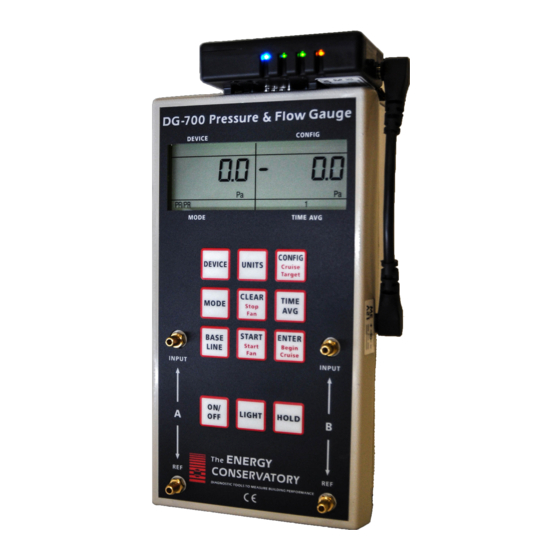
Chapter 1 Feature Summary 1.3 Gauge Face and Buttons Selected test device Selected test device (for air configuration (for air flow flow measurements on measurements on Channel B) Channel B) Channel A Reading Channel B Reading Selected Time Averaging Selected Operating Mode (for both Channels) Display Hold Indicator Low Battery Indicator... -
Page 11: Input/Output Ports On The Dg-700
1.4.a USB and Serial Communication Ports: The DG-700 contains both a USB and a DB-9 serial communication port, either of which can be used to create a 2- way communication link between the gauge and a computer. This communication link can be used (along with TEC software) to conduct automated Blower Door tests and to data log both pressure channels. -
Page 12: Overview Of The Time Averaging Feature
1.5 Overview of the Time Averaging Feature The DG-700 has a choice of 4 time averaging periods which are applied to both measurement channels. When the gauge is turned on, the default time averaging period is 1 second average. To change the selected time averaging period, press the TIME AVG button. -
Page 13: Overview Of The Baseline Pressure Measurement Feature (Channel A)
Chapter 1 Feature Summary 1.6 Overview of the Baseline Pressure Measurement Feature (Channel A) The Baseline feature on Channel A allows the user to measure and record a baseline pressure reading, and then display the baseline adjusted pressure on the gauge. For purposes of this manual a baseline pressure reading is defined as a pressure measurement made under a specific operating condition, which will be used to determine the change in pressure created by a change in the operating condition. -
Page 14: Restarting The Baseline Measurement
1.7 Auto-Off Feature In order to preserve battery life, the DG-700 gauge will automatically shut off if no keys are pressed for 2 hours. The auto-off feature can be disabled by simultaneously pressing the CLEAR and ENTER buttons. The auto-off feature is automatically re-enabled whenever the gauge is turned off and then back on. -
Page 15: Chapter 2 Pressure/Pressure Mode
1 second average. Each channel on the DG-700 measures the pressure difference between either of the top Input pressure taps and its corresponding bottom Reference pressure tap. The gauge can monitor and display both positive and negative pressure readings (i.e. -
Page 16: Changing The Time Averaging Period
Pressure/Pressure Mode 2.4 Changing the Time Averaging Period The DG-700 has a choice of 4 time averaging periods which are applied to both pressure measurement channels. The default time averaging period is 1 second average. To change the selected time averaging period, press the TIME AVG button. - Page 17 Chapter 2 Pressure/Pressure Mode subtracted from the current Channel A pressure measurement). The icon “ADJ” appears in the Channel A display to indicate that the baseline adjusted pressure reading is displayed. The time averaging period for the gauge reverts back to whatever period was selected prior to pressing the BASELINE button. Note: At this point, Channel B also reverts back to displaying an unadjusted pressure reading.
-
Page 18: Chapter 3 Pressure/Flow Mode
Model 3 (110V) Minneapolis Blower Door. The default time averaging period is 1 second average. 3.3 Changing the Selected Test Device and Configuration The DG-700 can display air flow from the following Energy Conservatory test devices on Channel B: ... -
Page 19: Lo" Displayed On Channel B
3.5 Changing the Air Flow Units When in the PR/ FL operating mode, the DG-700 can display air flow readings on Channel B in units of CFM, m /hr, or l/s. The default air flow unit is CFM. To change the air flow unit for Channel B, press the UNITS button. -
Page 20: Entering Baseline Readings Into Tectite Software When Using The Baseline Feature
Channel B displays the flow through the Blower Door fan. In the screen to the right, the DG-700 is measuring an actual building depressurization – 48.6 Pascals caused by the 3,564 CFM of air flow through the Blower Door fan (open fan). -
Page 21: Chapter 4 Pressure/Flow @ 50 And @ 25 Modes
@25, cm @25). airtightness test. Note: Appendix A contains Quick Guides for using the DG-700 to conduct one-point building and duct system airtightness tests using the @50 and @25 features. 4.2 Overview of Pressure/Flow @ 50 and @ 25 Modes ... -
Page 22: Benefits Of Using The @ 50 And @ 25 Modes
4.4 “-----”or “LO” Displayed on Channel B Whenever “-----” or “LO” appears on Channel B in the PR/ FL @ 50 or @ 25 modes, the DG-700 can not calculate a reliable leakage estimate. The messages “-----” and “LO” appear on Channel B under the following three conditions: ... -
Page 23: Changing The Leakage Units
Pressure/Flow @ 50 and @ 25 Modes 4.5 Changing the Leakage Units When in the Pressure/Flow @ 50 or @ 25 operating modes, the DG-700 can display leakage results on Channel B in units of CFM@, m /hr@, l/s@, in @, and cm @. -
Page 24: B @ 25 Mode
(CFM50) Note: Leakage areas calculated by the DG-700 are Equivalent Orifice Leakage Areas (EOLA), which are defined as the area of a sharp edged hole that would leak at the same flow rate as the estimated leakage rate, when the hole is subjected to the target test pressure (e.g. - Page 25 Chapter 4 Pressure/Flow @ 50 and @ 25 Modes Table 4.1: Error in Leakage Estimate for @ 50 Mode Actual exponent “n” 0.55 0.65 0.75 21.4% 14.9% 7.7% 0.0% -8.4% -17.5% Test 16.5% 11.3% 5.8% 0.0% -6.2% -12.8% Pressure in Pa (Channel A) 12.8% 8.8%...
-
Page 26: Chapter 5 Pressure/Air Handler Flow Mode
Duct Blaster fan. readings from Channel A. Note: Appendix A contains a Quick Guide for using the DG-700 with the Pressure/Air Handler Flow feature. 5.2 Overview of Pressure/Air Handler Flow Mode The Pressure/Air Handler Flow mode is a specialized mode used to measure air handler flow with a TrueFlow Air Handler Flow Meter or a Duct Blaster fan. -
Page 27: Or "Lo" Displayed On Channel B
5.4 “-----”or “LO” Displayed on Channel B Whenever “-----” or “LO” appears on Channel B in the Step 2 part of the PR/ AH procedure, the DG-700 can not display a reliable air handler flow estimate. The messages “-----” and “LO” appear on Channel B under the following three conditions: ... -
Page 28: Step 2: Measuring The Tfsop And Adjusted Air Handler Flow
Connect a piece of tubing to the static pressure probe. Connect the other end of the tubing to the Channel A Input tap on the DG-700. The Channel A Reference tap should be connected to the inside of the building, or it can be connected to an unconditioned zone containing the air handler provided that the zone remains at the same pressure as the building during the test. -
Page 29: Flow Resistance Correction Factors Used In The Dg-700
5.8 Flow Resistance Correction Factors Used in the DG-700 The following equation is used to calculate the flow resistance correction factor used by the DG-700 in the PR/ AH mode: 0.50... -
Page 30: Chapter 6 Pressure/Velocity Mode
The following equations are used to calculate air velocity from a pitot tube connected to Channel B. Note: The pitot tube should be set up to measure velocity pressure in order for the DG-700 to correctly display air velocity readings. -
Page 31: Chapter 7 Servicing And Maintenance
7.1.a Calibration: The DG-700 is calibrated at our factory prior to being shipped. A sticker on the back of the gauge case will indicate the date of calibration, as well as the next recommended recalibration date. Under normal operation, we recommend that the gauge be recalibrated once every two years. -
Page 32: Troubleshooting/Resetting The Dg-700
Chapter 7 Servicing and Maintenance 7.3 Troubleshooting/Resetting the DG-700 If the DG-700 gauge locks up or otherwise appears to be displaying inconsistent readings, try the following steps to reset the gauge. Simply turn the gauge off for 5 seconds and then turn it back on (using the ON/OFF button). -
Page 33: Appendix Aquick Guides For Using The Dg-700 With Energy Conservatory Test Devices
If your DG-700 gauge and fan speed control are compatible for Cruise Control, install the fan control cable into the 3.5 mm communication jacks located on the top of the DG-700 and on the side of the speed controller (otherwise skip this step). - Page 34 “-----” or “LO” appearing on Channel B Whenever “-----” or “LO” appears on Channel B in the PR/ FL @ 50 Mode, the DG-700 can not calculate a reliable leakage estimate. The messages “-----” and “LO” appear on Channel B under the following three conditions: “-----”...
-
Page 35: One-Point 25 Pascal Total Leakage Duct Pressurization Test Using The Seried B Minneapolis Duct Blaster And Dg-700 Digital Gauge
Cruise Control, install the fan control cable into the 3.5 mm communication jacks located on top of the DG-700 and on the side of the speed controller (otherwise skip this step). Prepare the duct system and house for the Test. - Page 36 “-----” or “LO” appearing on Channel B Whenever “-----” or “LO” appears on Channel B in the PR/ FL @ 25 Mode, the DG-700 can not calculate a reliable leakage estimate. The messages “-----” and “LO” appear on Channel B under the following three conditions: “-----”...
-
Page 37: Using The Trueflow Air Handler Flow Meter And The Dg-700 Digital Gauge
Appendix A Quick Guides for Using the DG-700 with Energy Conservatory Test Devices A.3 Using the TrueFlow Air Handler Flow Meter and the DG-700 Digital Gauge Measure the Normal System Operating Pressure (NSOP) with the existing filter in place. Locate the air handler system filter and replace if it is dirty. - Page 38 Connect the Metering Plate to the DG-700. Connect the tubing from the installed metering plate to the DG-700. Connect the Red ("total pressure grid") tubing connection to the Channel B Input pressure tap. Connect the Green ("static pressure grid") tubing connection to the Channel B Reference pressure tap.
-
Page 39: Dg-700 Connections Needed To Conduct Automated Blower Door Tests
• A fan control cable to connect the fan control output jack on the DG-700 to the communication jack on the side of the Blower Door fan speed controller. Note: If your Blower Door speed controller does not have a communication jack on the side of the controller box, you will need to purchase a new speed controller. - Page 40 COM3 is a custom communication port created by successfully installing the USB drivers for the DG-700 gauge. (Note: In order for a custom device communication port to be listed under the Ports icon, the DG-700 gauge must be connected to your computer.)
- Page 41 Connect the DG-700 to the Blower Door fan speed controller using the fan control cable. Plug one end of the cable into the 3.5 mm fan control output jack on the top of the DG-700, and plug the other end of the cable into the communication jack on the side of the fan speed controller box.
- Page 42 Appendix A Quick Guides for Using the DG-700 with Energy Conservatory Test Devices Communication Cable (USB or 9 pin Serial) To Computer Building Pressure Green Hose (A Reference) Fan Pressure Red Hose (B Input) Fan Control Cable Fan Power To Power Source...
-
Page 43: Using The Dg-700'S Cruise Control Feature
During this test, Cruise Control on the Blower Door’s DG-700 will maintain a contant 25 Pa building pressure while the DG-700 gauge connected to the Duct Blaster fan maintains a constant 0 Pa pressure in the duct system. •... - Page 44 Channel A. The fan will slowly start increasing speed until the pressure reading on Channel A matches the Cruise target pressure. The fan will simply run at full speed if the target pressure can not be achieved. Whenever the DG-700 is calling for full fan speed, the gauge will emit a beeping sound.
Need help?
Do you have a question about the DG-700 and is the answer not in the manual?
Questions and answers