
Subscribe to Our Youtube Channel
Summary of Contents for Dillenger KT-LCD3
- Page 1 KT-LCD3 User Manual eBike Special Meter English Please read through carefully before use...
-
Page 2: Preface
PREFACE This manual aims to help the user understand and familiarise themselves with the meter function, operation of the meter, how to set the project parameters, how to achieve the best match of the three (motor, controller, and meter) to improve electronic control performance of the electric motor. - Page 3 Button Box Dimensions Main Material and Colour The KT-LCD3 and button box are primarily constructed of polycarbonates (PC) and are of a dark gray or white colour. Wiring Schematic...
-
Page 4: Table Of Contents
Contents Preface Outlook and Size Installation Instruction Function Overview Display Content Button Definition Basic Operation On/Off Display Interface Battery Capacity Indicator PAS Ratio Power Push Function Cruise Function Backlight and Headlights Motor Operating Power and Temperature Ambient Temperature Single Data Clearing Automatically Prompt Interface User Setting Project General Project Setting... - Page 5 P5 Power Monitoring Setting C Parameter Setting C1 Throttle Start-Up Setting C2 Motor Phase Classification Coding Mode C3 Power Assist Ratio Gear Initialization C4 Handlebar Function Setting C5 Handlebar Function Setting C6 Handlebar Function Setting C7 Cruise Function Setting C8 Motor Operating Temperature Display Setting C9 Startup Password Setting C10 Restore Default Setting C11 Meter Attribute Setting...
-
Page 6: Installation Instruction
While the vehicle is off, connect the necessary wiring and check to make sure all connections are firmly attached. Finally, remove the protection film from the display. Ø 31.8 Handlebar Diameter Install Ø 22.2 Handlebar Diameter Install Installed KT-LCD3... -
Page 7: Function Overview
FUNCTION OVERVIEW KT-LCD3 meter provides a variety of functions such as vehicle controls and vehicle status digitized displays to meet the trip demands. ◊ Trip time display (with displays of a single trip time (TM) and total trip time (TTM));... -
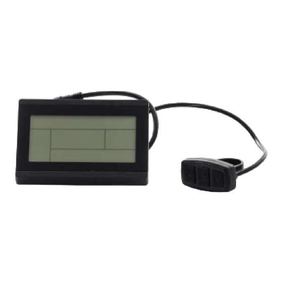
Page 8: Button Definition
BUTTON DEFINITION KT-LCD3 meter adopts the structural form with part design between the main part and operating buttons. There are three buttons on the operating panel of the box, which are icons of button (UP), button (DOWN) and button (POWER). - Page 9 Real-Time Trip Speed (Km/H) Power Assist 6Km/H Push Function Single Trip Distance (DST) Motor Operation Power Environment Temperature Backlight and Headlights Brake Status Cruise Function (CRUISE) Motor Running Temperature...
- Page 10 Display 2: To enter display 2, press the button whilst in display 1. The interface will display as shown below. Display 2 Total Trip Time (TTM) Total Trip Distance (ODO) Single Average Speed (AVS) Motor Operating Temperature Once the vehicle is in riding mode, after five seconds display 2 automatically reverts to display 1.
- Page 11 Display 3: To enter display 3, press the button whilst in display 2. The interface will display as shown below. Display 3 Real-Time Voltage (VOL) Single Maximum Speed (MXS) Once the vehicle is in riding mode, after five seconds the single maximum speed will return to real-time speed (Km/H) as shown below.
-
Page 12: Battery Capacity Indicator
Display of Power-Assist Battery Capacity Indicator The KT-LCD3 can identify 24V, 36V, 48V battery capacities when used with supporting controllers. When the battery capacity is over 70%, four bars from the battery indicator will be displayed. As the battery capacities drop, the bars will change accordingly. Once the power capacity is less than 15%, the battery indicator will be empty and show zero bars. -
Page 13: Power Push Function
Power Push Function Users can use power push function for assistance in vehicle take-off. Hold button and the motor will provide power until vehicle reaches 6 Km/H. The meter assist function icon will flash indicating the function is active. By releasing the button, the function will be revoked. -
Page 14: Motor Operating Power And Temperature
Motor Operating Power and Temperature Whilst vehicle is in use, real time feedback of input power to the motor is displayed on the meter. The operating temperature of the motor can be displayed with supporting sensors installed in the inner motor to output the temperature for signal detection. When the motor operating temperature exceeds the warning value, temperature display flashes to alarm the rider. -
Page 15: Automatically Prompt Interface
Automatically Prompt Interface Error Code Display: When there are issues with the electronic control system of the vehicle, the meter will automatically display (flicker) a fault code. This cannot be removed until fault is fixed. Refer to Error Code & Definition Table for reference. Motor operating temperature alarm: When the motor operating temperature exceeds the warning value, the motor operating temperature display flashes to alarm the rider, whilst the controller will provide the appropriate protection to the motor. -
Page 16: User Setting Project
1. If no button operation occurs for 60 seconds whilst in a settings menu, the KT-LCD3 will discard changes and return to display 1. To exit at any moment, hold and the meter will discard any unsaved changes and revert to display 1. -
Page 17: Wheel Diameter
Wheel Diameter While in the general project setting, cycle through the menu using the button until the values of “DST” are flashing. Use the button and button to scroll through the selection of the following wheel diameters: 6, 8, 10, 12, 14, 16, 18, 20, 22, 24, 26, 700C and 28 inches. -
Page 18: P Parameter Setting
Rounding to a full number is necessary. The P1 setting ranges between 1 and 255. P2 Wheel Speed Pulse Signal Setting The P2 parameter setting will display on the meter after the P1 parameter setting has been selected and confirmed. The KT-LCD3 will display as follows: P2 Display... -
Page 19: P3 Power Assist Control Setting
P3 Power Assist Control Setting The P3 parameter setting will display on the meter after the P2 parameter setting has been selected and confirmed. The KT-LCD3 will display as follows: P3 Display P3 parameters affect the power assist control setting. When the value is set to 0, the throttle is dependent on the PAS Gear Ratio. -
Page 20: P5 Power Monitoring Setting
P5 Power Monitoring Setting The P5 parameter setting will display on the meter after the P4 parameter setting has been selected and confirmed. The KT-LCD3 will display as follows: P5 Display The P5 Parameter is power monitoring mode. When the value is set to 0, the power monitoring is in "real-time voltage"... -
Page 21: C1 Throttle Start-Up Setting
C1 Throttle Start-Up Setting The C1 parameter setting will display on the meter after the P Parameter settings. The KT-LCD3 will display as follows: C1 Display C1 settings are the power assist sensor parameters. Its definition is shown in the following table. -
Page 22: C2 Motor Phase Classification Coding Mode
C2 Motor Phase Classification Coding Mode The C2 parameter setting will display on the meter after C1 settings. The KT-LCD3 will display as follows: C2 Display C2 parameters set the different phases of the motor when using a sine wave drive. The default value is 0, indicating that the used Quantum motor phase is standard. -
Page 23: C4 Handlebar Function Setting
C4 Handlebar Function Setting The C4 parameter setting will display on the meter after C3 settings. The KT-LCD3 will display as follows: C4 Display C4 settings are for the handlebar functions. The setting range is 0-4. This is accompanied by a table below, defining each value. -
Page 24: C6 Handlebar Function Setting
Maximum Current Value ÷ 1.10 Maximum Current Value C6 Handlebar Function Setting The C6 parameter setting will display on the meter after C5 settings. The KT-LCD3 will display as follows: C6 Display C6 settings are for the meter's backlight brightness. The default value is 3 and the setting range is 1-5. -
Page 25: C7 Cruise Function Setting
C7 Cruise Function Setting The C7 parameter setting will display on the meter after C6 settings. The KT-LCD3 will display as follows: C7 Display The cruise function settings can be found in C7. Refer to the following table for definitions of C7 values. -
Page 26: C9 Startup Password Setting
C9 Startup Password Setting The C9 parameter setting will display on the meter after C8 settings. The KT-LCD3 will display as follows: C9 Display C9 is the settings for password feature upon startup. The default value is 0. Refer to the following table for definition of the function. -
Page 27: C10 Restore Default Setting
C10 Restore Default Setting The C10 parameter setting will display on the meter after C9 settings. The KT-LCD3 will display as follows: C10 Display C10 restores the KT-LCD3 meter to default settings. Refer to table below for definitions. C10 Value... -
Page 28: C12 Controller Minimal Voltage Setting
As data source for copying parameters, the meter transfers the new LCD3 parameter to other meters C12 Controller Minimal Voltage Setting The C12 parameter setting will display on the meter after C11 settings. The KT-LCD3 will display as follows: C12 Display C12 parameters are settings for the controller's minimum operating voltage (voltage shortage value). -
Page 29: C13 Abs Brakes And Anti-Charge Control Setting
C13 ABS Brakes and Anti-Charge Control Setting The C13 parameter setting will display on the meter after C12 settings. The KT-LCD3 will display as follows: C13 Display C13 parameters are settings for the ABS braking strength and anti-charge control. Refer to the following table for definitions of each C13 value. -
Page 30: C14 Power Assist Tuning Setting
Set parameters (including general project parameters, P parameters and C parameters) of any KT-LCD3 meter can be copied to another KT-LCD3 meter. This can be done via C11 Meter Attribute Setting, where the meter can become a data source. Use special wiring cables to configure the meter as shown below. -
Page 31: Version Information
Special Wiring Cable Correctly configure and wire the meters and provide a power supply of 48V, 36V or 24V (VB + positive power supply). Hold button of the source meter until start up. Within 5 seconds, simultaneously hold button and button for 2 seconds. -
Page 32: Contact Us
CONTACT US Dillenger HQ 3/13 Olympic Circuit Southport QLD 4215 AUSTRALIA Phone: 07 5532 9235 dillenger.zendesk.com www.dillengerelectricbikes.com.au © Dillenger 2016...
Need help?
Do you have a question about the KT-LCD3 and is the answer not in the manual?
Questions and answers