
Summary of Contents for PG Drives Technology VR2 series
- Page 1 PG DRIVES TECHNOLOGY VR2 SERIES WHEELCHAIR CONTROL SYSTEM OPERATION, INSTALLATION & PROGRAMMING SK77898/2...
- Page 2 All rights reserved. This manual is furnished under copyright and may only be used in accordance with the terms laid out by PG Drives Technology. The information in this manual is furnished for informational use only, is subject to change without notice, and should not be construed as a commitment by PG Drives Technology.
-
Page 3: Table Of Contents
VR2 C DRIVES TECHNOLOGY ONTROL YSTEM TABLE OF CONTENTS About this manual ..........................ICONS ................................Chapter 1 - Operation ..................... 1 Introduction ..........................General ............................Handling ....................Operating Conditions ................Cleaning ....................Controls ............................On/Off Button and Battery Gauge ............Locking / Unlocking the Wheelchair ............ - Page 4 VR2 C ONTROL YSTEM DRIVES TECHNOLOGY Battery Gauge Steps Up ................ Battery Gauge Flashes Rapidly (even with the joystick released) ..Self-Help Guide ..................Slow or sluggish movement ..............Speed / Profile Indicator is Steady ............8.7.1 Speed Indication ..................8.7.2 Profile Indication ..................
- Page 5 VR2 C DRIVES TECHNOLOGY ONTROL YSTEM Connector Kits ..................Wiring ............................General ....................Wire Gauge and Types ................Battery Wiring ..................Motor Wiring ................... Solenoid Brake Wiring ................Drive Motors ........................... Batteries ............................Battery Charging ......................... Off-board Charging ................On-board Charging ................Inhibits ............................
- Page 6 VR2 C ONTROL YSTEM DRIVES TECHNOLOGY Drive Profiles ................... Speed Parameters ......................Acceleration ..................Deceleration ..................Turn Acceleration ................... Turn Deceleration ................... Forward Speed ..................Reverse Speed ..................Turning Speed ..................Power ..................... Number of Drive Profiles ................. 2.10 Minimum Acceleration ................2.11 Minimum Deceleration ................
- Page 7 VR2 C DRIVES TECHNOLOGY ONTROL YSTEM Inhibit Parameters ......................Inhibit 2 Threshold Level ................. Inhibit 2 Speed Limit in Band x ............... Inhibit 2 Operation ................. Inhibit 2 Debounce ................Seat Reversal ..................Inhibit 3 Threshold Level ................. Inhibit 3 Speed Limit in Band x ............... Inhibit 3 Operation .................
- Page 8 VR2 C ONTROL YSTEM DRIVES TECHNOLOGY Memory Functions ......................Read Timer .................... Clear Timer .................... Read System Log ................... Erase System Log ................... Chapter 4 - Lighting......................77 Introduction ..........................Controls ............................Actuator Button and LEDs ..............2.1.1 Wheelchairs with One Actuator ..............2.1.2 Wheelchairs with Two Actuators ..............
- Page 9 VR2 C DRIVES TECHNOLOGY ONTROL YSTEM 2.3.2 Wheelchairs with Two Actuators ..............Maximum Speed Button and Indicator ..........2.4.1 Maximum Speed Indicator ................2.4.2 Maximum Speed Button ................Installation ..........................Connection ..........................Connetion to the VR2 Dual Attendant ........... Joystick Orientation ......................Diagnostics ..........................
- Page 10 VR2 C ONTROL YSTEM DRIVES TECHNOLOGY Trip Type 1 - Low Battery Voltage ............Trip Type 2 – Left Motor Disconnected ........... Trip Type 3 – Left Motor Wiring Trip ............Trip Type 4 – Right Motor Disconnected ..........Trip Type 5 - Right Motor Wiring Trip ............Trip Type 6 –...
- Page 11 VR2 C DRIVES TECHNOLOGY ONTROL YSTEM 2.11 Crimping ....................2.12 Wiring – General ..................2.13 Battery Wiring ..................2.14 Drive Motors ................... 2.15 Off-board Charging ................2.16 On-board Charging ................2.17 Production Test ..................2.18 Programming – Introduction ..............2.19 Safety Fences ..................2.20 Brake Fault Detect .................
-
Page 12: About This Manual
Chapter 8 - Specifications Lists all the Electrical Specifications of the VR2 Control System. ICONS PG Drives Technology will be abbreviated to PGDT throughout the manual. Throughout the manual icons are used to draw the reader’s attention. The icons used are: Note - A general point for best practice. -
Page 13: Chapter 1 - Operation
1 - O DRIVES TECHNOLOGY HAPTER PERATION CHAPTER 1 OPERATION SK77898/2... - Page 14 VR2 C ONTROL YSTEM DRIVES TECHNOLOGY SK77898/2...
-
Page 15: Introduction
1 - O DRIVES TECHNOLOGY HAPTER PERATION Introduction The relevant contents of this chapter should be included in the wheelchair operating guide. Further copies are available from PGDT in either written or disk (Adobe PDF) format. Copies should not be made without the express permission of PG Drives Technology. -
Page 16: Controls
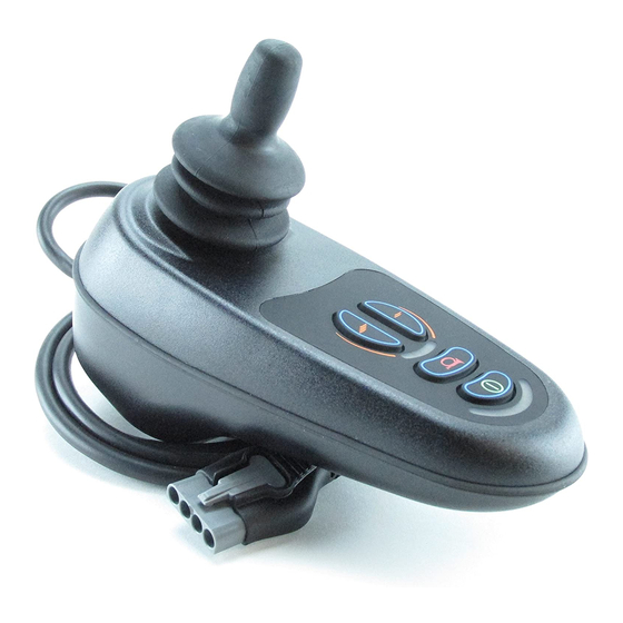
VR2 C ONTROL YSTEM DRIVES TECHNOLOGY Controls The VR2 control system has four versions of the front control panel – with and without actuator control. Most of the controls are common to both versions, however, the actuator buttons are only included on VR2 control systems with seat actuator control. Each of the controls is explained within this section. -
Page 17: On/Off Button And Battery Gauge
1 - O DRIVES TECHNOLOGY HAPTER PERATION VR2 CONTROL BUTTONS Battery Gauge On/Off Button Horn Button Maximum Speed / Profile Indicator Speed / Profile Decrease Button Speed / Profile Increase Button Actuator Buttons On/Off Button and Battery Gauge The on/off button applies power to the control system electronics, which in turn supply power to the wheelchair’s motors. -
Page 18: Locking / Unlocking The Wheelchair
VR2 C ONTROL YSTEM DRIVES TECHNOLOGY Locking / Unlocking the Wheelchair The VR2 control system can be locked to prevent unauthorized use. The locking method is via a sequence of key presses and joystick movements, as detailed below. To lock the wheelchair. While the control system is switched on, depress and hold the on/off button. -
Page 19: Horn Button
1 - O DRIVES TECHNOLOGY HAPTER PERATION This is an indicator that shows the selected drive profile. There may be up to 5 drive profiles available, this depends on the programming of the control system (refer to Chapter 3). For details of how to select drive profiles, see sections 3.6 and 3.7. Horn Button The horn will sound while this button is depressed. -
Page 20: Charger And Programmer Socket
Connection of other electrical devices may damage the control system or affect the E.M.C. performance of the wheelchair. The control system’s warranty will be voided if any device other than a PG Drives Technology Programmer, or the battery charger supplied with the wheelchair, is connected into this socket. -
Page 21: Getting Ready To Drive
1 - O DRIVES TECHNOLOGY HAPTER PERATION Getting Ready to Drive Operate the on/off switch. The battery gauge will blink then remain on after a • second. Check that the maximum speed control is set to a level which suits you. •... -
Page 22: Precautions For Use
VR2 C ONTROL YSTEM DRIVES TECHNOLOGY Precautions for Use In the event of the wheelchair moving in an unexpected way RELEASE THE JOYSTICK. This action will stop the wheelchair under any circumstances. Hazards Do not drive the wheelchair: Beyond restrictions indicated in your wheelchair user manual, for example •... - Page 23 1 - O DRIVES TECHNOLOGY HAPTER PERATION any kind arising from failure to comply with this condition. It is the responsibility of the chair manufacturer to ensure that the wheelchair complies with appropriate National and International E.M.C legislation. PGDT accepts no liability for losses of any kind arising from failure to comply with this condition.
-
Page 24: Safety Checks
VR2 C ONTROL YSTEM DRIVES TECHNOLOGY Safety Checks The electronic circuits in your control system have been designed to be extremely safe and reliable. The on-board microcomputer carries out safety checks at up to 100 times per second. To supplement this safety monitoring you should carry out the following periodic checks. -
Page 25: Control System Status Indication
1 - O DRIVES TECHNOLOGY HAPTER PERATION Control System Status indication The battery gauge and maximum speed /profile indicator show the status of the control system. A number of supposedly defective control systems returned to us are subsequently found to operate correctly. This indicates that many reported faults are due to wheelchair problems rather than the control system. - Page 26 VR2 C ONTROL YSTEM DRIVES TECHNOLOGY Below is a list of self-help actions. Try to use this list before you contact your service agent. Go to the number in the list which matches the number of flashing bars and follow the instructions. If the problem persists after you made the checks described above contact your service agent.
-
Page 27: Slow Or Sluggish Movement
1 - O DRIVES TECHNOLOGY HAPTER PERATION An Actuator trip is indicated. If more than one actuator is fitted, 8 Bar + A check which actuator is not working correctly. Check the actuator wiring. Slow or sluggish movement If the wheelchair does not travel at full speed or does not respond quickly enough, and the battery condition is good, check the maximum speed setting. -
Page 28: Battery Gauge
VR2 C ONTROL YSTEM DRIVES TECHNOLOGY Battery Gauge The battery gauge is included to let you know how much charge is left in your batteries. The best way for you to use the gauge is to learn how it behaves as you drive the wheelchair. -
Page 29: Battery Charging
1 - O DRIVES TECHNOLOGY HAPTER PERATION Battery Charging To charge the wheelchair batteries connect the charger plug into the battery charging socket on the VR2. You will not be able to drive the wheelchair when the charger is connected. To connect the charger plug, ensure the single pin is at the bottom, as shown in the following illustration, then offer the charger plug to the VR2 in a horizontal orientation. -
Page 30: Programming
VR2 C ONTROL YSTEM DRIVES TECHNOLOGY condition could result in a burns hazard or fire hazard. PGDT accepts no liability for losses of any kind arising from failure to comply with this condition. Only use the battery charger that has been supplied with your wheelchair. -
Page 31: Joystick Knobs
It is possible to replace the cable and the joystick, by following instructions laid down by PG Drives Technology. Refer to Chapter 6 - Servicing. -
Page 32: Warranty
VR2 C ONTROL YSTEM DRIVES TECHNOLOGY Warranty The VR2 control system is covered by a warranty period defined by the wheelchair manufacturer. For details of the warranty period, please contact your service agent. The warranty will be void if the VR2 control system has: Not been used in accordance with the VR2 control system Technical Manual, •... -
Page 33: Chapter 2 - Installation
2 - I DRIVES TECHNOLOGY HAPTER NSTALLATION CHAPTER 2 INSTALLATION SK77898/2... - Page 34 VR2 C ONTROL YSTEM DRIVES TECHNOLOGY SK77898/2...
-
Page 35: Documentation
2 - I DRIVES TECHNOLOGY HAPTER NSTALLATION Documentation VR2 Operation Study Chapters 1,2 and 3. It is important that the operation information in these chapters is supplied with the wheelchair, either as part of the wheelchair user handbook or as a separate document. This chapter sets out the installation conditions that must be complied with in order to meet the safety requirements of TÜV (Germany), ISO7176-14 and EN12184. -
Page 36: Soft-Stop
VR2 C ONTROL YSTEM DRIVES TECHNOLOGY programming or the VR2 Control System. Soft-Stop The VR2 has a programmable value called Soft Stop Rate which sets the emergency stopping distance. You must ensure that the emergency stopping distance is within the distance specified for the country in which the wheelchair will be used. TÜV Product Service (Germany) specify the distance to be as stated in EN12184. -
Page 37: Immobilizing The Wheelchair
ISO 7176-14 requires you to provide a means of preventing the use of the wheelchair while the batteries are being charged. The charger socket and on-board charger connection fitted to the PG Drives Technology VR2 control systems include an inhibit facility. Refer to section 9 for details. -
Page 38: Mounting
VR2 C ONTROL YSTEM DRIVES TECHNOLOGY Mounting Joystick Module The VR2 Joystick Module has two holes for mounting on the underside. The holes are tapped with an M5 thread allowing for a maximum screw penetration depth of 8mm (5/16”) JOYSTICK MOUNTING HOLE POSITIONS 42mm / 1.65"... -
Page 39: Position
2 - I DRIVES TECHNOLOGY HAPTER NSTALLATION POWER MODULE MOUNTING HOLE POSITIONS 161.0mm / 6.34" 3.2.2 Position The Power Module must be mounted in a position where it is not exposed to conditions of water or dust above those specified in ISO7176/9. The Power Module is designed to withstand levels of shock and vibration experienced when mounted to the chassis of a wheelchair. -
Page 40: Connections
PGDT accepts no liability for losses of any kind arising from failure to comply with this condition. Connector Kits The connector kits can be purchased from PG Drives Technology, or from Intech directly. Intech’s details are as below. Intech (UK) - Page 41 2 - I DRIVES TECHNOLOGY HAPTER NSTALLATION VR2 POWER MODULE CONNECTIONS INH-2 MOTOR 1 BATTERY MOTOR 2 Brake +ve Brake -ve Brake +ve Brake -ve Motor +ve Motor -ve Motor +ve Motor -ve 12V/24V 12V/24V CIRCUIT BRAKE BRAKE BREAKER INHIBIT 2 INH-2 Function Inhibit 2...
- Page 42 VR2 C ONTROL YSTEM DRIVES TECHNOLOGY Only use the exact tools as specified. For details of automatic crimp tools contact Intech. SK77898/2...
-
Page 43: Wiring
2 - I DRIVES TECHNOLOGY HAPTER NSTALLATION Wiring General Study the data sheet for the control system to identify: The output current, ratings and restrictions • The connector pin assignments • Recommendations for the cross-sectional area, ratings and materials for wiring are given in the table in section 4.2. -
Page 44: Battery Wiring
VR2 C ONTROL YSTEM DRIVES TECHNOLOGY These recommendations are derived from well proven field experience of various international wheelchair manufacturers. Nevertheless, manufacturers must confirm these recommendations by carrying out suitable tests. Keep wire lengths as short as possible. Connections Wire Gauge Battery Wires 4.0mm Motor Wires... -
Page 45: Motor Wiring
2 - I DRIVES TECHNOLOGY HAPTER NSTALLATION Motor Wiring In order to detect the disconnection of a motor while the wheelchair is in motion, the brake current must pass through the same connectors as the motor current, so that disconnection of either motor will interrupt the brake circuit and trip the control system. -
Page 46: Drive Motors
VR2 C ONTROL YSTEM DRIVES TECHNOLOGY Drive Motors The control system is designed to be connected to permanent magnet DC motors, fitted with suitable gearboxes and solenoid brakes. In order to optimize the performance of the wheelchair, the control system must be matched to the motor terminal impedance. -
Page 47: Batteries
2 - I DRIVES TECHNOLOGY HAPTER NSTALLATION with the electrical and dynamic characteristics of their specific target vehicles. The characteristics of one type of control system may not be compatible with a different, unauthorized chair. Failure to observe this warning could result in an unsafe set-up for the wheelchair user and may create a fire hazard depending on the motors, wiring, connectors and circuit breakers installed on the unauthorized... -
Page 48: Battery Charging
VR2 C ONTROL YSTEM DRIVES TECHNOLOGY Battery Charging The VR2 control systems supports both on-board and off-board methods of battery charging. While the battery is being charged the VR2’s TruCharge display will continuously ripple or step upwards. The two methods of charging are described in the following sections. -
Page 49: On-Board Charging
2 - I DRIVES TECHNOLOGY HAPTER NSTALLATION On-board Charging The VR2 control systems have a 3 way connector for connection to an on-board battery charger. Refer to section 4 for connector details. The maximum permissible charging current is 12A rms. For details of how to provide a suitable inhibit function, refer to section 9.1. -
Page 50: Actuator Control
VR2 C ONTROL YSTEM DRIVES TECHNOLOGY Actuator Control The VR2 control system has the facility for 2 actuator output channels. Each actuator channel can supply a maximum current of 12A. The VR2 provides automatic end- stop detection for each actuator, see section 10.1. To ensure correct operation of the user controls for 1 or 2 actuator applications, it is necessary to program the control system accordingly. - Page 51 2 - I DRIVES TECHNOLOGY HAPTER NSTALLATION control system to detect the end-stop. Please contact PGDT if you are unsure. Large values of capacitance should not be connected across the control system’s actuator outputs, as electrical resonance could occur which may affect control system operation.
-
Page 52: Production Tests
VR2 C ONTROL YSTEM DRIVES TECHNOLOGY Production Tests Perform the following tests, in order, on each wheelchair before dispatch. • These tests should be conducted in an open space and a restraining device such as a seat belt should always be used. -
Page 53: Test Drive
2 - I DRIVES TECHNOLOGY HAPTER NSTALLATION left and right. 11.6 Test Drive • Drive the wheelchair and make sure that it operates correctly for all positions of the user controls. 11.7 Soft-Stop Test Drive the wheelchair at full forward speed and switch the control system off. •... -
Page 54: Electromagnetic Compatibility (E.m.c.)
VR2 C ONTROL YSTEM DRIVES TECHNOLOGY Electromagnetic Compatibility (E.M.C.) The VR2 control system series has been tested for compliance with the EMC requirements of EN12184. The guidelines in this section will help you to make sure that your wheelchair installation will meet the requirements of the directive. 12.1 Emissions A typical wheelchair and VR2 installation have been type tested and have passed... -
Page 55: Battery Gauge
2 - I DRIVES TECHNOLOGY HAPTER NSTALLATION Battery Gauge For optimum accuracy of the battery gauge and low battery indicator, the control system should be programmed with the approximate nominal capacity of the wheelchair battery. However, accuracy is not greatly affected if the programmed type and capacity do not closely match the battery. - Page 56 VR2 C ONTROL YSTEM DRIVES TECHNOLOGY SK77898/2...
-
Page 57: Chapter 3 - Programming
3 - P DRIVES TECHNOLOGY HAPTER ROGRAMMING CHAPTER 3 PROGRAMMING SK77898/2... - Page 58 VR2 C ONTROL YSTEM DRIVES TECHNOLOGY SK77898/2...
-
Page 59: Introduction
This chapter gives an overview of the programmable parameters within the VR2 control system. The VR2 can be programmed with a PP1 handheld programmer or a PG Drives Technology PC Programmer. This chapter does not give details of how to make adjustments, for these details please refer to the relevant documentation for the programmer you are using. -
Page 60: Parameters
VR2 C ONTROL YSTEM DRIVES TECHNOLOGY Parameters The parameters have been separated into workable groups for easy referencing. Speeds - Section 2 Inhibit – Section 6 Acceleration Inhibit 2 Threshold Levels Inhibit 2 Speed Limit Bands Deceleration Inhibit 2 Operation Turn Acceleration Inhibit 2 Debounce Turn Deceleration... -
Page 61: Safety Fences
3 - P DRIVES TECHNOLOGY HAPTER ROGRAMMING Motor Swap Torque Tremor Damping Memory Functions – Section 9 Read System Log Clear System Log Read Timer Clear Timer Safety Fences Limits (or fences) can be applied to some dealer accessible programmable parameters. - Page 62 VR2 C ONTROL YSTEM DRIVES TECHNOLOGY maximum speed /profile increase and decrease buttons are then used to switch between the available profiles. Although a number of Drive Profiles can be set to one, the operation is the same as setting to 0 but without the ability to change maximum speed settings.
-
Page 63: Speed Parameters
3 - P DRIVES TECHNOLOGY HAPTER ROGRAMMING Speed Parameters Acceleration Adjusts the value for forward and reverse acceleration of the wheelchair. Adjustable in steps of 1 from 0 to 100. A higher value gives faster acceleration. This programmed value of acceleration occurs when speed setting 5 is selected. -
Page 64: Power
VR2 C ONTROL YSTEM DRIVES TECHNOLOGY A higher value gives a faster speed. If Drive Profile 0 is selected then the minimum value occurs when speed setting 1 is selected, and the maximum value occurs when speed setting 5 is selected. Power Sets the power of the wheelchair. -
Page 65: Minimum Turn Acceleration
3 - P DRIVES TECHNOLOGY HAPTER ROGRAMMING This percentage of the Deceleration value occurs when the VR2 speed setting is at See following example. Deceleration = 80 and Minimum Deceleration = 25% Deceleration at step 1 = 25% of 80 = 20 Speed settings 2, 3 and 4 will interpolate linearly between 20 and 80 Deceleration at step 2 = 35 Deceleration at step 3 = 50... - Page 66 VR2 C ONTROL YSTEM DRIVES TECHNOLOGY SK77898/2...
-
Page 67: Actuator Parameters
3 - P DRIVES TECHNOLOGY HAPTER ROGRAMMING Actuator Parameters Number of Actuators Sets the number of actuators to be connected to the VR2 control system. This value must be set correctly in order to get the most informative and user-friendly method of actuator control. -
Page 68: Actuator End Stop Detection
VR2 C ONTROL YSTEM DRIVES TECHNOLOGY Actuator End Stop Detection This can protect the actuator motor from high levels of current over extended periods of time. This parameter can be set to On or Off. The parameters Actuator End Force and Actuator Current Limit Time Out are activated and stop the actuator motors. -
Page 69: Operation Parameters
3 - P DRIVES TECHNOLOGY HAPTER ROGRAMMING Operation Parameters Sleep Timer Sets the period of time before the control system will turn itself off if the wheelchair is not driven. The time can be set between 1 and 10 minutes in steps of 1 minute. If the time is set to 0 the system will never turn itself off. - Page 70 VR2 C ONTROL YSTEM DRIVES TECHNOLOGY Means the buttons are not active while the wheelchair is being driven, so the joystick must be released and the wheelchair at rest before maximum speed setting adjustments (or different drive profile selections) can be made. SK77898/2...
-
Page 71: Battery Parameters
3 - P DRIVES TECHNOLOGY HAPTER ROGRAMMING Battery Parameters Low Battery Flash Level This parameter sets the point at which the VR2's TruCharge battery gauge starts to flash slowly to warn of a low battery condition. Adjustable between 1 and 10 in steps of 1. This corresponds to the number of bars shown on the battery gauge. - Page 72 VR2 C ONTROL YSTEM DRIVES TECHNOLOGY Voltage Cut Out Level before the control system ceases to operate. Programmable from 1 to 255 seconds in steps of 1 second. SK77898/2...
-
Page 73: Inhibit Parameters
3 - P DRIVES TECHNOLOGY HAPTER ROGRAMMING Inhibit Parameters The VR2 contains two highly versatile inhibit inputs that can be configured to provide drive inhibit, speed limiting and actuator inhibit functions. These inputs are referred to as Inhibit 2 and Inhibit 3. Inhibit 2 is via a dedicated 2-way connector on the Power Module. -
Page 74: Inhibit 2 Operation
VR2 C ONTROL YSTEM DRIVES TECHNOLOGY Each is programmable between 0% and 100% in steps of 1%. The value in each band’s parameter sets the wheelchair’s maximum driving speed when the VR2’s Inhibit 2 input is in that band. For example, if Inhibit 2 Speed Limit in Band 3 is set to 0%, then the drive will be fully inhibited when the connection to Inhibit 2 is of a resistance within the range of Band For a more detailed example of actuator inhibits, refer to section 6.15.1 Inhibit 2 Operation... -
Page 75: Inhibit 3 Speed Limit In Band X
3 - P DRIVES TECHNOLOGY HAPTER ROGRAMMING 100% corresponds to a resistance of 10KOhm or greater, including an open-circuit, being connected to pin 1 of Inhibit 3. 0% corresponds to a short-circuit between pins 2 and 3 of Inhibit 3. Each of the Level Threshold parameters can be set to a value of 0% to 100% in steps of 1% meaning the range of each band is programmable. -
Page 76: Inhibit 1: Alarm
VR2 C ONTROL YSTEM DRIVES TECHNOLOGY 6.10 Inhibit 1: Alarm This parameter sets whether there is an audible alarm given if VR2 Inhibit 1 is active. Inhibit 1 is the inhibit associated with the off-board charging socket on the front face of the VR2. -
Page 77: Actuator Channel 2 Up Inhibit And Actuator Channel 2 Down Inhibit
3 - P DRIVES TECHNOLOGY HAPTER ROGRAMMING Inhibit in Inhibit 3 Band 3 Each parameter can be set to yes or no. Means that particular actuator channel direction of movement will be inhibited when the relevant inhibit input is in that band. For example, If Actuator Channel 1 Up: Inhibit in Inhibit 2 Band 3 is set to yes, then Actuator Channel 1 Up direction will be inhibited when the connection to Inhibit 2 is of a resistance within the range of Band 3. -
Page 78: Actuator Inhibit Examples
VR2 C ONTROL YSTEM DRIVES TECHNOLOGY VR2 INHIBIT BANDS Band 3 - 4K4 = 44% Band 2 Band 1 - 2K2 = 22% Band 0 Upper Level Threshold Middle Level Threshold Lower Level Threshold This gives a band arrangement as below. As good practice, the threshold limits have been chosen so the actual resistance values that trigger a change are in the approximate center of the bands, thereby eliminating the risk of a system erroneously switching between bands. - Page 79 3 - P DRIVES TECHNOLOGY HAPTER ROGRAMMING Actuator Channel 2 Up: Inhibit in Inhibit 2 Band 0 Inhibit in Inhibit 2 Band 3 Inhibit in Inhibit 3 Band 0 Inhibit in Inhibit 3 Band 3 Actuator Channel 2 Down: Inhibit in Inhibit 2 Band 0 Inhibit in Inhibit 2 Band 3 Inhibit in Inhibit 3 Band 0 Inhibit in Inhibit 3 Band 3...
- Page 80 VR2 C ONTROL YSTEM DRIVES TECHNOLOGY VR2 THRESHOLD - BAND RELATIONSHIP 100% Band 3 Upper Threshold Level Band 2 Middle Threshold Level Band 1 Lower Threshold Level Band 0 This programming means that the Up movement will be inhibited when the Inhibit 2 input in Band 0, i.e.
-
Page 81: General Parameters
3 - P DRIVES TECHNOLOGY HAPTER ROGRAMMING General Parameters Fast Brake Rate Adjusts the deceleration rate used while fast braking. Fast braking is when the joystick is pulled to the reverse position to make a faster stop. Adjustable between 1 and 100 in steps of 1. If this value is set lower than the Deceleration value, then the Deceleration value will be used for fast braking. -
Page 82: K10 Programming Restriction
VR2 C ONTROL YSTEM DRIVES TECHNOLOGY K10 Programming Restriction Sets whether the VR2 is field programmable or not. The parameter can be set to on or off. Means the VR2 cannot be programmed with dealer access programmers, such as a PP1a or PC Programmer. Means the VR2 can be programmed with these types of devices. -
Page 83: Motor Parameters
3 - P DRIVES TECHNOLOGY HAPTER ROGRAMMING Motor Parameters Current Limit Max., Current Limit Min., Current Foldback - Threshold, Time, Level, & Temperature These parameters affect the VR2’s current output with relationships to time and internal VR2 temperature. The parameters associated with the Motors are: Current Limit Max. - Page 84 VR2 C ONTROL YSTEM DRIVES TECHNOLOGY Example 1- Time / Threshold / Level: The parameters Threshold, Time and Level can be used to protect the motors from overheating. If the motor current exceeds the value set by Threshold for a period set by Time, then the VR2’s current output will be reduced to a value set by Level After a fixed reset period of 5 x Current Foldback Time, the current output will be allowed to return to the full current, if demanded.
-
Page 85: Motor Compensation
3 - P DRIVES TECHNOLOGY HAPTER ROGRAMMING 3 - Current Foldback Temp. This parameter sets the temperature within the control system at which the current starts to reduce linearly. VR2 CURRENT/TEMPERATURE RELATIONSHIP Current Temperature 80 C It is important that the maximum values in the table shown below are not exceeded for the VR2 model you are working with. -
Page 86: Invert M1 Direction
VR2 C ONTROL YSTEM DRIVES TECHNOLOGY The chair manufacturer is responsible for ensuring that the control system is matched to the motor resistance. Failure to do this may result in poor control characteristics, which in extreme instances can make a chair uncontrollable and potentially unsafe. -
Page 87: Torque
3 - P DRIVES TECHNOLOGY HAPTER ROGRAMMING Means the motor outputs will be swapped. Means they will not. Torque The Torque parameter boosts the current to the motors at low speed settings. If the motor is stalled, for example, the wheelchair is stuck against an obstacle, such as a door threshold;... -
Page 88: Memory Functions
VR2 C ONTROL YSTEM DRIVES TECHNOLOGY Memory Functions The VR2 has a timer and a diagnostic log. These can be read and cleared using the PP1a Programmer or the PC Programmer. Read Timer The VR2 has a timer which records how long the wheelchair is in use. The timer runs whenever the joystick is moved away from the center position, and stops when the joystick is returned. -
Page 89: Chapter 4 - Lighting
4 - L DRIVES TECHNOLOGY HAPTER IGHTING CHAPTER 4 LIGHTING SK77898/2... - Page 90 VR2 C ONTROL YSTEM DRIVES TECHNOLOGY SK77898/2...
-
Page 91: Introduction
4 - L DRIVES TECHNOLOGY HAPTER IGHTING Introduction This section of the manual describes the operation, installation and programming differences generated by the VR2 lighting system. The VR2 lighting system comprises of: VR2-L: VR2 fitted with lighting control buttons, and connection to a VR2 lighting module (VR2-LM) Controls There are common controls between the VR2 and VR2-L control system which operate... - Page 92 VR2 C ONTROL YSTEM DRIVES TECHNOLOGY VR2-L USER CONTROLS Joystick Control Panel Charger and Programmer Socket Front Control Panel Details No Actuators With Actuators SK77898/2...
- Page 93 4 - L DRIVES TECHNOLOGY HAPTER IGHTING VR2 CONTROL BUTTONS Battery Gauge On/Off Button Horn Button Maximum Speed / Profile Indicator Speed / Profile Decrease Button Speed / Profile Increase Button Actuator Button Lights Button Hazards Button Indicator Buttons SK77898/2...
-
Page 94: Light Button Indicator
VR2 C ONTROL YSTEM DRIVES TECHNOLOGY To re-enter drive mode depress the actuator button again or depress either speed button Light Button Indicator To turn on the wheelchair’s lights operate this button, the associated LED will illuminate continuously. If the LED flashes a short circuit in the lighting circuit has been detected. Depress the light button to turn off the lights and associated LED. -
Page 95: Lighting Module Installation
4 - L DRIVES TECHNOLOGY HAPTER IGHTING Lighting Module Installation Mounting The lighting module should be mounted vertically, with the connector sockets pointing down, using M3.5 (Europe) or #6-40 (USA) screws. The lighting module must be mounted in a position where it is not exposed to conditions of water or dust above those specified in ISO7176/9. -
Page 96: Connection
VR2 C ONTROL YSTEM DRIVES TECHNOLOGY Connection The lighting module has three connector sockets. Refer to the illustration in section 3.1. 3.2.1 Socket 1 This socket accepts a Hirose DF7 series 3 way connector for the control of the LEFT side lights. - Page 97 Crimps DF7-1618SCF PG Drives Technology: Connector Boot P76720 As an alternative a complete kit can be purchased from PG Drives Technology. PG Drives Technology: 3 Way Connector Kit: D50301 PGDT recommends the use of 0.75 mm / 20 AWG Tri-Rated Equipment wire or equivalent.
- Page 98 VR2 C ONTROL YSTEM DRIVES TECHNOLOGY LIGHTING MODULE WIRING DETAIL 1 2 3 INDICATORS LIGHTS LIGHTS INDICATORS 1 2 3 LOOKING AT LIGHTING MODULE Connection Function Pin1 Ground Pin2 Lights Pin3 Indicators SK77898/2...
-
Page 99: Programming
4 - L DRIVES TECHNOLOGY HAPTER IGHTING Programming The VR2-L contains 3 extra programmable parameters which are described below. Lamp Voltage Adjusts the operating voltage for the wheelchair’s lighting system. You can select either 12V or 24V. The wheelchair’s lights and indicators should be fitted with lamps of the corresponding value. - Page 100 VR2 C ONTROL YSTEM DRIVES TECHNOLOGY SK77898/2...
-
Page 101: Chapter 5 - Dual Attendant System
5 - D DRIVES TECHNOLOGY HAPTER CHAPTER 5 DUAL ATTENDANT SYSTEM SK77898/2... - Page 102 VR2 C ONTROL YSTEM DRIVES TECHNOLOGY SK77898/2...
-
Page 103: Introduction
5 - D DRIVES TECHNOLOGY HAPTER Introduction The VR2 dual attendant control system consists of a VR2 Joystick Module, Power Module and a Dual Attendant Module. This allows the drive and actuator functions of the wheelchair to be controlled either by the occupant, or by an attendant from another location on the wheelchair. -
Page 104: Controls
VR2 C ONTROL YSTEM DRIVES TECHNOLOGY Controls Refer to the following illustration for the dual module control layout. DUAL MODULE USER CONTROLS Control Panel Joystick Knob Option Joystick Control Panel Details Joystick This controls the speed and direction of the wheelchair. Push the joystick in the direction you wish to go. -
Page 105: Control Button And Indicator
5 - D DRIVES TECHNOLOGY HAPTER DUAL MODULE CONTROL BUTTONS Control Button and Indicator Actuator Button Speed Indicator Maximum Speed Button Control Button and Indicator 2.2.1 Control Indicator This shows which joystick has control. If the red wheelchair light is on, the wheelchair occupant’s joystick has control. -
Page 106: Maximum Speed Button And Indicator
VR2 C ONTROL YSTEM DRIVES TECHNOLOGY button once illuminates the LEFT LED, and deflection of the joystick forwards or backwards will adjust the actuator connected to that channel. Selection between the two actuators is achieved by deflecting the joystick to the left and right. As the actuator selected changes then so will the LED, which illuminates. -
Page 107: Installation
5 - D DRIVES TECHNOLOGY HAPTER Installation The dual module has four holes for mounting on the underside. Refer to the following illustration for details of the hole positions. The holes are tapped with an M5 thread to a depth of 10mm (3/8"). The dual module is not sensitive to mounting orientation except where it is exposed to water or dust. -
Page 108: Connection
VR2 C ONTROL YSTEM DRIVES TECHNOLOGY Connection Secure all cables to the wheelchair frame over as much of their length as is practical. Connetion to the VR2 Dual Attendant The VR2 dual attendant system is connected to the VR2 Dual Attendant Control System via a designated cable as shown below using the cable supplied. - Page 109 5 - D DRIVES TECHNOLOGY HAPTER Including a VR2 Dual Attendant Module into a lighting configuration. VR2 DUAL ATTENDANT SYSTEM CONNECTION CONFIGURATION VR2-L LIGHTING MODULE DUAL MODULE To Power ATTENDANT Module MODULE INTERMEDIATE CABLE SK77898/2...
-
Page 110: Joystick Orientation
VR2 C ONTROL YSTEM DRIVES TECHNOLOGY Joystick Orientation Reorientation of the joystick is only required when the dual attendant system has been mounted on a wheelchair so that the control buttons are not facing in the wheelchairs forward drive direction. Reorientation is achieved as follows: Ensure the Control of the VR2 has been set to the dual attendant system. -
Page 111: Diagnostics
3 LEDs there is an internal trip in the dual module. The dual module must be disconnected and returned to PG Drives Technology. 8 bars will be flashing on the VR2, but it can be reset by disconnecting the dual module and switching the control system off and on again. - Page 112 VR2 C ONTROL YSTEM DRIVES TECHNOLOGY SK77898/2...
-
Page 113: Chapter 6 - Servicing & Diagnostics
6 - S & D HAPTER ERVICING IAGNOSTICS DRIVES TECHNOLOGY CHAPTER 6 SERVICING & DIAGNOSTICS SK77898/2... - Page 114 VR2 C ONTROL YSTEM DRIVES TECHNOLOGY SK77898/2...
-
Page 115: Servicing
6 - S & D DRIVES TECHNOLOGY HAPTER ERVICING IAGNOSTICS Servicing Introduction The VR2 Joystick Module has been designed and constructed to allow field replacements of some key components. The replaceable components are: The Joystick The Joystick Cable. The Keypad Keypad Joystick Cable... -
Page 116: Joystick Replacement
VR2 C ONTROL YSTEM DRIVES TECHNOLOGY Joystick Replacement Retaining Top Section Screws x5 Gasket Base Section Base Plan View 1.2.1 Joystick Removal • Isolate the Joystick Module by disconnecting the Joystick Cable from the Power Module. Remove the 5 retaining screws from the underside of the Joystick Module. •... - Page 117 6 - S & D DRIVES TECHNOLOGY HAPTER ERVICING IAGNOSTICS Joystick Knob Gaiter Top Plan View Joystick Retaining Screws x2 Ribbon Cable Top Plan View Joystick SK77898/2...
-
Page 118: Fitting A Joystick
VR2 C ONTROL YSTEM DRIVES TECHNOLOGY 1.2.2 Fitting a Joystick Ensure Gaiter/Rubber-boot is positioned with the flange firmly against the underside of the Top Section. Ensure the joystick is in the correct orientation. The notch on the joystick plate should lineup with the Key in the Top Section. •... -
Page 119: Joystick Cable Replacement
6 - S & D DRIVES TECHNOLOGY HAPTER ERVICING IAGNOSTICS If the replacement or the calibration sequence has been unsuccessful the TruCharge display will flash 7 bars. Refer to Diagnostics Chapter. If the Joystick does not operate correctly, or if the calibration sequence does not appear, then run through the following: •... -
Page 120: Fitting A Joystick Cable
VR2 C ONTROL YSTEM DRIVES TECHNOLOGY Cable Charger Connection & Cable 1.3.2 Fitting a Joystick Cable • Insert the new Charger Socket and Cable into the plastic case. • Attach the cable from the new Charger Socket and Cable onto the PCB •... -
Page 121: Keypad Replacement
6 - S & D DRIVES TECHNOLOGY HAPTER ERVICING IAGNOSTICS Keypad Replacement • Disconnect Joystick Cable from the Power Module • Gently lift the top corner of the keypad, with a scalpel. • Remove the damaged keypad. • Ensure surface area is clear, clean and free of adhesive. •... -
Page 122: Diagnostics
VR2 C ONTROL YSTEM DRIVES TECHNOLOGY Diagnostics Introduction The primary objective of this section is to assist service personnel in finding the likely area of a detected fault within the whole wheelchair electrical system. It is important to realize that even though the control system is signaling a fault, it may not be the control system itself that is defective. -
Page 123: Detecting A Trip Has Occurred
6 - S & D DRIVES TECHNOLOGY HAPTER ERVICING IAGNOSTICS Detecting a Trip has Occurred Firstly observe the control system’s TruCharge (battery gauge) display. This will behave as described in one of the following sections. 2.3.1 Flashing rapidly The control system is tripped. •... -
Page 124: Control System Will Not Switch On
VR2 C ONTROL YSTEM DRIVES TECHNOLOGY considered critical enough to force a trip or the control system cannot detect the condition. 2.4.1 Control system will not switch on • Check the battery connections to the control system. If these appear to be good, then the Power Module may be defective, refer to section 5. -
Page 125: Using A Programmer To Read The Trip Code
6 - S & D DRIVES TECHNOLOGY HAPTER ERVICING IAGNOSTICS 2.5.2 Using a programmer to read the trip code If you connect a programmer while the TruCharge display is flashing rapidly, then a four digit trip code will be displayed. The trip code can be referred to the trip types using the table in section 3. -
Page 126: Trip Types And Their Possible Causes
VR2 C ONTROL YSTEM DRIVES TECHNOLOGY Trip Types and Their Possible Causes Once the trip type has been established, refer to the relevant section below for further information. Trip Trip Description & Reference Code Type 1320 Refer to section (3.16) 1505 Left Solenoid Brake Trip (3.9) 1506... -
Page 127: Trip Type 1 - Low Battery Voltage
6 - S & D DRIVES TECHNOLOGY HAPTER ERVICING IAGNOSTICS Trip Type 1 - Low Battery Voltage This occurs when the control system detects that the battery voltage has fallen below 16V. Check the condition of the batteries and the connections to the control system. If the trip is still present after the batteries and connections have been checked, then the Power Module may be defective. -
Page 128: Trip Type 6 – Charger Connected
VR2 C ONTROL YSTEM DRIVES TECHNOLOGY outputs. In this instance, this section will refer to the left hand motor. Consult the wheelchair manufacturer for more details. Trip Type 6 – Charger Connected This occurs when the control system detects that an off-board charger is connected. Check that the battery charger is disconnected. -
Page 129: Trip Type 10 - High Battery Voltage
6 - S & D DRIVES TECHNOLOGY HAPTER ERVICING IAGNOSTICS 3.10 Trip Type 10 - High Battery Voltage This occurs when the control system detects that the battery voltage has risen above 35V. The most common reasons for this are overcharging of the battery or bad connections between the control system and the batteries. -
Page 130: Current Limit Active
VR2 C ONTROL YSTEM DRIVES TECHNOLOGY If the trip is still present after the above checks have been made, then the Power Module may be defective. Refer to Section 5. 3.16 Current Limit Active This occurs when the control system operates above the Current Limit Threshold for a period of time greater than the Current Limit Time. -
Page 131: Basic Tests
6 - S & D DRIVES TECHNOLOGY HAPTER ERVICING IAGNOSTICS Basic Tests After a repair has been completed, the following tests should be carried out. These are minimum recommendations, depending on the nature of the original trip then additional tests may be required. These tests are a minimum recommendation only. -
Page 132: Gradient Test
VR2 C ONTROL YSTEM DRIVES TECHNOLOGY directions, ensuring the drive is comfortable and easy to control for the user. Repeat the above but with the speed control set to maximum. Gradient Test Before carrying out this test ensure another person is present to prevent the wheelchair from tipping backwards. -
Page 133: Servicing Of Defective Units
6 - S & D DRIVES TECHNOLOGY HAPTER ERVICING IAGNOSTICS Servicing of Defective Units Excluding the items listed in Section 1 of this Chapter there are no serviceable parts, in any of the PGDT control systems. Consequently, any defective units must be returned to PGDT or a PGDT approved service organization for repair. - Page 134 VR2 C ONTROL YSTEM DRIVES TECHNOLOGY SK77898/2...
-
Page 135: Chapter 7 - Warning Summary
7 - W DRIVES TECHNOLOGY HAPTER ARNING UMMARY CHAPTER 7 WARNING SUMMARY SK77898/2... - Page 136 VR2 C ONTROL YSTEM DRIVES TECHNOLOGY SK77898/2...
-
Page 137: Introduction
UNSAFE CONDITIONS for the user of a wheelchair or affect the reliability of the control system. PG Drives Technology accepts no liability for losses of any kind arising from failure to comply with any of the conditions in the warnings listed below. -
Page 138: How To Read A Trucharge Battery Gauge
VR2 C ONTROL YSTEM DRIVES TECHNOLOGY Do not operate the control system if the chair behaves erratically, or shows abnormal signs of heating, sparks or smoke. Turn the control system off at once and consult your service agent. PGDT accepts no liability for losses of any kind arising from failure to comply with this condition. -
Page 139: Programming
7 - W DRIVES TECHNOLOGY HAPTER ARNING UMMARY Ensure that the charger plug pins are of the correct polarity to be compatible with the pin polarity shown on the control system’s specific data sheet. Failure to observe this condition could result in a burn hazard or fire hazard. PGDT accepts no liability for losses of any kind arising from failure to comply with this condition. -
Page 140: Warranty
VR2 C ONTROL YSTEM DRIVES TECHNOLOGY If the control system is damaged in any way, or if internal damage may have occurred through impact or dropping, have the product checked by qualified personnel before operating. PGDT accepts no liability for losses of any kind arising from failure to comply with this condition. - Page 141 7 - W DRIVES TECHNOLOGY HAPTER ARNING UMMARY 2.11 Crimping Defective or poor quality crimps may affect the warranty of the controller. PGDT accepts no liability for losses of any kind arising from failure to comply with this condition. Chapter 2 section 4.0.1. 2.12 Wiring –...
-
Page 142: Drive Motors
VR2 C ONTROL YSTEM DRIVES TECHNOLOGY 2.14 Drive Motors The chair manufacturer is responsible for ensuring that the control system is matched to the motor resistance. Failure to do this may result in poor control characteristics, which in extreme instances can make a chair uncontrollable and potentially unsafe. -
Page 143: On-Board Charging
7 - W DRIVES TECHNOLOGY HAPTER ARNING UMMARY Ensure that the charger plug pins are of the correct polarity to be compatible with the pin polarity shown on the control system’s specific data sheet. Failure to observe this condition could result in a burn hazard or fire hazard. PGDT accepts no liability for losses of any kind arising from failure to comply with this condition. - Page 144 VR2 C ONTROL YSTEM DRIVES TECHNOLOGY 2.18 Programming – Introduction Programming should only be conducted by healthcare professionals with in-depth knowledge of PGDT control systems. Incorrect programming could result in an unsafe set-up of a wheelchair for a user. PGDT accept no responsibility for losses of any kind if the programming of the control system is altered from the factory pre-set values.
-
Page 145: Torque
7 - W DRIVES TECHNOLOGY HAPTER ARNING UMMARY compatible with the originals that the control system was designed to match. Failure to do this may result in poor control characteristics, which in extreme instances can make a chair uncontrollable and potentially unsafe. PGDT accepts no liability for losses of any kind arising from failure to comply with this condition. -
Page 146: Mounting
VR2 C ONTROL YSTEM DRIVES TECHNOLOGY 2.25 Mounting It is possible for the case temperature of the Lighting Module to rise above 41°C (107°F). For this reason the Lighting Module should be fixed in a position where it cannot be touched by the wheelchair user. -
Page 147: Batteries Discharge Very Quickly
7 - W DRIVES TECHNOLOGY HAPTER ARNING UMMARY 2.30 Batteries Discharge Very Quickly The ambient temperature has a significant effect on battery capacity. Therefore, if the temperature is lower than normal the wheelchair’s range will be reduced. In this situation, the TruCharge battery gauge still gives an accurate state-of- charge reading. - Page 148 VR2 C ONTROL YSTEM DRIVES TECHNOLOGY SK77898/2...
-
Page 149: Chapter 8 - Specifications
6 - S DRIVES TECHNOLOGY HAPTER PECIFICATIONS CHAPTER 8 SPECIFICATIONS SK77898/2... - Page 150 VR2 C ONTROL YSTEM DRIVES TECHNOLOGY SK77898/2...
-
Page 151: Electrical Specifications
6 - S DRIVES TECHNOLOGY HAPTER PECIFICATIONS Electrical Specifications Supply Voltage: 24Vdc Operating Voltage: 16Vdc to 35Vdc Peak Voltage: 35Vdc Reverse Battery Current: 40Vdc PWM Frequency: 20kHz ± 0.5% Brake Voltage: 12Vdc or 24Vdc Brake Current: 100mA min. 1A max. Charger Connector: Use only Neutrik NC3MX Batt. - Page 152 VR2 C ONTROL YSTEM DRIVES TECHNOLOGY SK77898/2...
Need help?
Do you have a question about the VR2 series and is the answer not in the manual?
Questions and answers
How do I reset the joystick control to original state.
To reset the joystick control for PG Drives Technology Pilot+ chin controls:
1. Ensure the unit is switched off.
2. Hold down the yellow 'mode' switch.
3. Displace the joystick away from the center.
4. While holding both, switch the unit on.
5. The battery indicator will ripple up and down.
6. Continue holding the 'mode' switch and joystick for 5 more seconds.
7. When the battery indicator flashes 7 bars, release the joystick and mode switch.
This process reconfigures joystick orientation without removing it or changing programmable settings.
This answer is automatically generated