Table of Contents
Advertisement
Quick Links
OPERATOR MANUAL
Please read carefully
before using the machine!
Store carefully for future
use!
This Operator Manual should be consi-
dered as part of the machine. Suppliers
of new and second-hand machines are
obliged to indicate in writing that the
Operator Manual has been delivered
with the machine.
Translation of the original
operating manual
e
5900660-
-en-0909
Advertisement
Table of Contents

Related Manuals for Rauch quantron e

Summary of Contents for Rauch quantron e
- Page 1 OPERATOR MANUAL Please read carefully before using the machine! Store carefully for future use! This Operator Manual should be consi- dered as part of the machine. Suppliers of new and second-hand machines are obliged to indicate in writing that the Translation of the original Operator Manual has been delivered operating manual...
-
Page 2: Technical Improvements
Preface Dear customer Your purchase of the control unit Quantron E for the AXIS fertiliser spreader indicates your confi- dence in our products. Thank you! We want to justify your trust. You have purchased a powerful and reliable control unit.control unit However, if any problems occur: Our Customer Service is al- ways ready to help. -
Page 3: Table Of Contents
Preparation of metering slide........19 Operation Quantron E Switching on the control unit . - Page 4 Table of Contents Field data ............62 4.7.1 Select field file.
-
Page 5: User Instructions
The operator manual is not intended to replace your own personal responsibil- ity as the owner and operator of the control units Quantron E. Brief instructions are supplied with the control unit Quantron E. If these are not included in the scope of supply please contact us. - Page 6 User instructions Danger levels in the safety precautions The danger level is identified by the signal word. The danger levels are classified as follows: n DANGER Type and source of the danger This note warns of a danger posing an immediate threat to the health and life of people.
-
Page 7: Instructions And Procedures
User instructions 1.2.2 Instructions and procedures Steps that the operator must carry out are shown as a numbered list. 1. Instruction for action step 1 2. Instruction for action step 2 Instructions that only have one step are not numbered. The same applies for ac- tion steps that do not have a specific sequence. - Page 8 User instructions...
-
Page 9: Layout And Function
Layout and function Layout and function Overview of the AXIS versions supported Function/Options AXIS Q AXIS W Ground speed dependent AXIS 20.1 Q spreading AXIS 30.1 Q AXIS 40.1 Q Weighing spreader AXIS 30.1 W AXIS 40.1 W ... -
Page 10: Layout Of The Control Unit - Overview
Layout and function Layout of the control unit - Overview Figure 2.1: Control unit Quantron E Designation Function Control panel Keys for operation of the unit and the display for ope- rating screens. V24 data port Serial interface (RS232) with LH 5000 and ASD protocol, designed for connection of an RS232 Y- cable for connecting to a remote terminal. -
Page 11: Controls, Keys
Layout and function Controls, keys Figure 2.2: Control panel on front of unit NOTICE The operator's manual describes the functions of the control unit Quantron E as of software version 3.30.00. Designation Function Start / Stop Starts and stops spreading. -
Page 12: Display
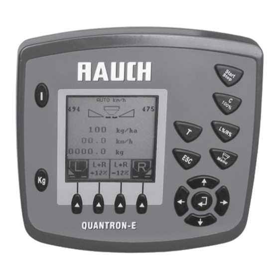
Layout and function Designation Function Navigation field 4 arrow keys and one Enter key for navigation in the menus and the input fields. Arrow keys for moving the cursor on the display or to highlight an input field. Enter key to confirm an input. ... - Page 13 Layout and function Figure 2.3: Display on the control unit (using the operating screen as an example) The icons and displays in the example have the following meaning: No. Icon / Display Meaning (in the example) Operating mode Shows the current operating mode. Auto km/h uses the radar signal or wheel signal ...
-
Page 14: Structural Overview Of Menu
Layout and function Structural overview of menu... -
Page 15: Attachment And Installation
Attachment and installation Attachment and installation Requirements for the tractor Before installing the control unit, check to make sure your tractor meets the fol- lowing requirements: Minimum voltage 11 V is essential at all times, even if multiple consumers are ... -
Page 16: 7-Pin Plug Connector
Connecting the control unit n CAUTION Note machine number The control unit Quantron E is calibrated at the factory for the fertiliser spreader with which it was delivered. Connect the control unit control unit to the correct ferti- liser spreader only. - Page 17 Attachment and installation Carry out the installation in the following order. Select a suitable position in the tractor cabin (in the driver's field of view) to attach the control unit. Install the control unit with the bracket in the tractor cabin. ...
- Page 18 Attachment and installation Standard schematic terminal diagram: km/h Figure 3.3: Schematic terminal diagram Quantron E (machine cable) [1] RS232 serial interface [2] 39-pin machine connector [3] Battery [4] Option (level sensor left/right) [5] 3-pin plug connector as per DIN 9680 / ISO 12369...
- Page 19 Attachment and installation Wheel sensor schematic terminal diagram: km/h Figure 3.4: Schematic terminal diagram Quantron E (machine cable) [1] RS232 serial interface [2] 39-pin machine connector [3] Battery [4] Option (level sensor left/right) [5] 3-pin plug connector as per DIN 9680 / ISO 12369...
- Page 20 Attachment and installation Machine cable schematic terminal diagram: km/h km/h Figure 3.5: Schematic terminal diagram Quantron E (machine cable) [1] RS232 serial interface [2] 39-pin machine connector [3] Battery [4] Option (level sensor left/right) [5] 3-pin plug connector as per DIN 9680 / ISO 12369...
-
Page 21: Preparation Of Metering Slide
CAUTION Observe the position of the metering slide The operation of the actuators by the Quantron E can damage the metering slide if the stop levers are incorrectly positioned. Always clamp the stop lever at the maximum scale position. - Page 22 Attachment and installation...
-
Page 23: Operation Quantron E
14). The voltage is at least 11 V. NOTICE The operator manual describes the functions of the control unit Quantron E as of software version 3.30.00. n CAUTION Risk of injury from discharged fertiliser Only for mineral fertiliser broadcasters equipped with electronic... - Page 24 Press the ON/OFF switch. After a few seconds, the start interface appears on the control unit. Then the boot menu is displayed for a few seconds. Then the operating screen appears. Figure 4.1: Start Quantron E [1] ON/OFF switch...
-
Page 25: Weighing - Tripcounter
Operation Quantron E Weighing - Tripcounter In this menu you can have the values of the spreading work carried out displayed and you can perform functions for the weighing operation. Press the kg key on the control unit. The Weighing-Tripcounter menu opens. -
Page 26: Trip Counter
Operation Quantron E 4.2.1 Trip counter You can find values for the completed spreading work (time, area, distance) with this menu. Figure 4.3: Trip counter menu [1] Display of spread amount since the last reset [2] Display of spread area since the last reset... -
Page 27: Remaining Fertiliser Volume
Operation Quantron E 4.2.2 Remaining fertiliser volume In the kg rest menu, you can call up the remaining fertiliser volume in the hop- per. The menu shows the possible area (ha) and distance (m) that can be spread with the remaining fertiliser volume. Both displays are calculated based on the fol-... - Page 28 Operation Quantron E Entering the remaining fertiliser volume when refilling (not with weighing spreader): 1. Switch from the Weighing-Tripcounter menu to the kg rest menu. The remaining fertiliser volume from the last spreading process appears in the display. 2. Fill the hopper.
-
Page 29: Weigh Quantity
Operation Quantron E 4.2.3 Weigh quantity In this menu you can weigh the fertiliser volume contained in the hopper and set the parameters for controlling the flow factor. NOTICE The Weigh Quantity function can only be requested if the fertiliser spreader being used is an AXIS W. - Page 30 the tractor is at a standstill the Quantron E is switched on. Weighing the fertiliser volume in the hopper: 1. Fill the hopper. A window appears in the display which shows the remaining fertiliser vo- lume.
- Page 31 Operation Quantron E Working with the weighed fertiliser quantity, topping up the hopper: 1. Tare the scales. 4.2.4: Machine tare, page 2. Select the fertiliser type. 4.4.6: Fertiliser chart, page 3. Fill the hopper. 4. Weigh the fertiliser quantity in the hopper.
-
Page 32: Machine Tare
Operation Quantron E 4.2.4 Machine tare In this menu, set the weighing value for the empty weighing spreader to 0 kg. NOTICE The Machine tare menu item can only be requested if the fertiliser spreader being used is an AXIS W. -
Page 33: Main Menu
Operation Quantron E Main menu Press the menu key in the operating screen. The main menu opens on the display. Figure 4.8: Quantron E Main menu The main menu shows the following submenus. Submenu Meaning Description Fertiliser settings... -
Page 34: Fertiliser Settings
Operation Quantron E Fertiliser settings You make the settings for the fertiliser and spreader operation in this menu. Switch from the main menu to the Fertiliser settings menu. Figure 4.9: Fertiliser settings menu Submenu Meaning/Possible values Description Name of fertiliser Selected fertiliser from private table. - Page 35 Operation Quantron E Submenu Meaning/Possible values Description Calibration start Request submenu for executing the cali- page 38 bration test. Spreading disc Selection list: Selection using type arrow keys Confirmation with Enter key Drop point L...
-
Page 36: Application Rate
Operation Quantron E How to select a submenu: 1. Highlight the submenu with the black bar in the display. The highlight bar can be moved up and down with the arrow keys. 2. Open the highlighted submenu with the Enter key. -
Page 37: Working Width
Operation Quantron E 4.4.2 Working width You can set the working width (in metres) in this menu. Figure 4.11:Working width menu Entering the working width: 1. Switch from the Fertiliser settings menu to the Working Width menu The working width currently set appears on the display. -
Page 38: Flow Factor
The calibration menus (page 38) permit the flow factor to be determined with the aid of the Quantron E and entered. Figure 4.12:Flow factor menu With the weighing spreader, the calculation of the flow factor is performed through dynamic weighing. However, the data can also be entered manually. - Page 39 Operation Quantron E NOTICE If your fertiliser is not listed in the fertiliser chart, input flow factor 1.00. In the AUTO km/h operating mode, we strongly recommend that you perform a calibration to precisely determine the flow factor for this fertiliser.
-
Page 40: Calibration Test
Operation Quantron E 4.4.4 Calibration test NOTICE On the weighing spreader the calibration test menu is blocked in the AUTO km/h + Auto kg operating mode; the menu point cannot be selected. In this menu, you can determine the flow factor on the basis of a calibration test and save it in the control unit. - Page 41 Operation Quantron E Figure 4.14:Working speed menu 4. Confirm the input by pressing the Enter key. The new value is saved in the operator panel. The Prepare calibration test screen opens. Figure 4.15:Prepare calibration test screen [1] Icon above function key F4 to select right spreading side...
- Page 42 Operation Quantron E Running calibration test: n WARNING Risk of injury when performing the calibration Rotating machine components and discharged fertiliser may cause injury. Before starting the calibration test make sure that all requirements have been met. Follow the Calibration sec- tion in the operating manual for the fertiliser spreader.
- Page 43 Operation Quantron E Figure 4.17:Input collected weight menu n WARNING Risk of injury from rotating machine components Contact with rotating machine components (shafts, hubs) may cause bruises, abrasions and crushing injuries. Body parts or objects may be caught or pulled in.
- Page 44 Operation Quantron E Recalculate flow factor 1. Weigh the spread fertiliser amount. 2. Input the weight of discharged fertiliser in the input field of the Input collected weight menu. See also 4.9.2: Input of values using the cursor keys, page 3.
-
Page 45: Drop Point (L+R)
Operation Quantron E 4.4.5 Drop point (L+R) When the Quantron E is connected to an AXIS 50.1 W fertiliser spreader, the drop point is actuated and adjusted electrically. NOTICE Entering the drop point with the AXIS 20.1, AXIS 30.1 or AXIS 40.1 is merely informative and does not affect the settings on the fertiliser spreader. -
Page 46: Fertiliser Chart
Operation Quantron E 4.4.6 Fertiliser chart You can create and manage fertiliser charts in this menu. NOTICE The selection of a fertiliser chart has an effect on the fertiliser settings, the con- trol unit and the fertiliser spreader. The setting of the application rate remains unaffected. - Page 47 Operation Quantron E NOTICE We recommend naming the fertiliser chart with the fertiliser name to improve the classification of the fertiliser chart. 7. Confirm the name input with the F4 key (OK). The name of the fertiliser chart is saved in the operator panel.
-
Page 48: Hopper Configuration
Operation Quantron E Hopper configuration You make the settings for the tractor and the fertiliser spreader in this menu. Switch from the main menu to the Hopper configuration menu. Figure 4.20:Hopper configuration menu Submenu Meaning Description Tractor (km/h) Determination or calibration of the speed page 47 signal. -
Page 49: Speed Calibration
Opening speed settings: In the control unit Quantron E, up to 4 different profiles for type and number of impulses can be saved. You give the profiles names (e. g. tractor name). Before spreading, check that the correct profile is open in the control unit. - Page 50 Operation Quantron E Recalibrating the speed signal: You can overwrite an existing profile or create a profile in an empty memory lo- cation. 1. Highlight the desired memory location with the function key below it in the Tractor (km/h) menu.
- Page 51 Operation Quantron E The number of impulses of the speed signal must still be specified below. If you know the exact number of impulses you can enter it directly: 7. Highlight the Imp/100m submenu and press the Enter key. The Impulses menu is displayed for manual input of the number of im- pulses.
-
Page 52: Auto / Man Mode
Operation Quantron E 4.5.2 AUTO / MAN mode By default you operate in AUTO mode. The control unit automatically controls the actuators as specified by the speed signal. Only work in manual mode if: there is no speed signal (radar or wheel sensor not available or defective), ... - Page 53 Procedure when spreading with Auto km/h + Auto kg: 1. Each time you switch on the Quantron E, use the kg button to switch to the Weigh Quantity menu and weigh the volume of fertiliser using Refill or New Fertiliser.
- Page 54 Operation Quantron E 5. Highlight the action carried out in the display: Refill: Continue spreading with the same fertiliser. The flow factor setting is retained. The remaining fertiliser volume is increased by the refilling volume New fertiliser: Flow factor set to 1.0 and a new flow factor regulation will ...
- Page 55 Select Auto km/h + Stat. kg: 1. Switch on the control unit Quantron E. 2. Fill the hopper with fertiliser. 3. Switch from the Hopper configuration menu to the AUTO/MAN operation menu.
- Page 56 Procedure when spreading with Auto km/h + Stat. kg: 1. Each time you switch on the Quantron E, use the kg button to switch to the Weigh Quantity menu and weigh the volume of fertiliser using Refill or New Fertiliser.
- Page 57 Automatic Mode (Auto km/h) a) Select Auto km/h: 1. Switch on the control unit Quantron E. 2. Switch from the Hopper configuration menu to the AUTO/MAN operation menu. 3. Highlight the AUTO km/h selection field.
- Page 58 Operation Quantron E b) Procedure when spreading with Auto km/h: 1. Carry out the fertiliser settings: Application rate (kg/ha) Working width (m) 2. Pour the fertiliser in. 3. Carry out a calibration test to determine the flow factor Take the flow factor from the fertiliser chart and enter it manually.
- Page 59 Operation Quantron E Manual Operation (MAN km/h) 1. Switch from the Hopper configuration menu to the AUTO/MAN operation menu. 2. Highlight the MAN km/h selection field. The Forward speed menu is displayed. 3. Input the value for the forward speed during spreading. Confirm the input by pressing the Enter key.
- Page 60 Operation Quantron E The metering slide opening can be changed manually during spreader operation in the MAN scale mode. Requirement: The metering slides are open (activation with the Start/Stop key). In the MAN Scale operating screen, the symbols for the part widths are filled ...
-
Page 61: Appl. Rate
Operation Quantron E 4.5.3 +/- appl. rate In this menu, you can specify a percentage volume change for the normal spreading type. The basis (100 %) is the pre-set value of the dispensing slider opening. NOTICE During operation you can use the button F2/F3 to change the spreading volume by the factor of the +/- volume at any time. -
Page 62: Fast Emptying
Operation Quantron E Fast emptying The Fast emptying menu can be selected to clean the machine after spreading or to discharge the remaining weight quickly. NOTICE Before starting fast emptying make sure that all requirements have been met. Observe the operating instructions for the fertiliser spreader (fast emptying). - Page 63 Operation Quantron E Run fast emptying: 1. Use the Function Button to select the desired part width. The selected part width is shown as a symbol in the display. 2. Press the Start/Stop button. Fast emptying is started.
-
Page 64: Field Data
Operation Quantron E Field data In this menu you can create and save up to 200 operating data files. Switch from the main menu to the Field Data menu. Figure 4.28:Field file menu Submenu Meaning Description Choose new file Selects a field file which is already saved. -
Page 65: Creating A New Field File
Operation Quantron E 4.7.2 Creating a new field file 1. In the Field data menu, select the Create New File entry and press the Enter key. The display shows a window for entering the file name or a note. - Page 66 Operation Quantron E 2. Select the Field data start field and press the Enter key. Recording starts. The Field data start display changes to Field data stop. The operating screen displays the recording icon. Figure 4.30:Recording symbol 3.
-
Page 67: Stopping Recording
3. Press the ESC key to return to the previous menu Press the Menu key to return to the Operating Screen. 4.7.5 Importing and exporting operating data The control unit Quantron E enables the operating data recorded to be imported or exported. 4.8.4: Data transmission, page ... -
Page 68: System / Test
Operation Quantron E System / Test This menu is used to created the test and system settings for the control unit. Switch from the main menu to the System / Test menu. Figure 4.31:System/Test menu pages 1 and 2... -
Page 69: Setting Language
2. Open the highlighted submenu with the Enter key. 4.8.1 Setting language In the control unit Quantron E there are 2 different language packages possi- ble. Each language package covers 12 predefined languages. The language package for your country is preloaded in the factory. -
Page 70: Display Config
Operation Quantron E 4.8.2 Display config. The display fields in the operating screen of the control unit can be configures as required. You can assign both display fields with the following values if desired: Ground speed Flow factor (FF) ... -
Page 71: Test / Diagnosis
Operation Quantron E 4.8.3 Test / Diagnosis In the Test/Diagnosis menu you can monitor the function of certain sensors/ac- tuators. NOTICE This menu serves only for information purposes. The list of the sensors depends upon the equipment level of the machine. - Page 72 Operation Quantron E Figure 4.35:Test/Diagnosis;Example: Weighing cells [1] Current fertiliser volume in left hand hopper [2] Fill level left, in percent [3] Fill level right in percent Figure 4.36:Test/Diagnosis; Example: Voltage [1] Current operating voltage [2] Functional range of the sensor Figure 4.37:Test/Diagnosis;...
-
Page 73: Data Transmission
Importing/exporting up to 200 See below operating data files Quantron E Transmission of the new soft- ware Importing operating data (PC to Quantron E) Requirements: Use the data stick supplied. Do not alter the directory structure on the data stick. ... - Page 74 Operation Quantron E Figure 4.39:Importing and exporting operating data 4. Press the Enter key. A message appears indicating that the current data will be deleted. Figure 4.40:Message prior to deletion of the files 5. Press the Start/Stop button. The bar indicates the progress of the transmission.
- Page 75 Operation Quantron E The consequences of importing the operating data are as follows: All operating data currently stored in the Quantron E is overwritten. If you have defined the application rate on the PC, the application rate is au- ...
-
Page 76: Service
Operation Quantron E 4.8.5 Service NOTICE An input code is required for settings in the Service menu. These settings can only be modified by authorised service personnel. As a general rule, we recommend that all settings in this menu are carried out... -
Page 77: Special Functions
Operation Quantron E Special functions 4.9.1 Text input In some menus freely editable text can be input. Figure 4.43:Text input menu [1] Input field [2] Delete the complete input [3] Arrow keys for navigation through the character field [4] Enter key to confirm input... -
Page 78: Input Of Values Using The Cursor Keys
Operation Quantron E Overwrite character: A single character can be overwritten by another character. A single character cannot be deleted. 5. Move the cursor by using the arrow keys to the position of the character to be deleted in the input field. -
Page 79: Alarm Messages And Possible Causes
Alarm messages and possible causes Alarm messages and possible causes Various alarm messages can be displayed on the control unitQuantron E display. Meaning of alarm messages Message in display Meaning Possible cause Error in the metering The actuator for the metering device cannot direction. - Page 80 Alarm messages and possible causes Message in display Meaning Possible cause Min.setting = 2.00 Reference to the range of values for the Max.setting = 50.00 working width. Value entered is not permitted. Min.setting = 0.40 Reference to the value range of the flow Max.setting = 1.90 factor.
-
Page 81: Clear Fault / Alarm
Alarm messages and possible causes Clear fault / alarm 5.2.1 Acknowledging alarm message: An alarm message is highlighted in the display and displayed with a warning icon. Figure 5.1: Alarm message (example: fertiliser settings) Acknowledging alarm message: 1. Correct the cause of the alarm message. Observe the operating manual of the fertiliser spreader and section 5.1: Meaning of alarm messages, page 2. - Page 82 Acknowledging alarm message: 1. Proceed as described in the previous paragraph. 2. Switch the control unit Quantron E off (ON/OFF) and then restart it. 3. Switch to the Weigh Quantity menu using the kg button. 4. Select the function New fertiliser.
-
Page 83: Special Equipment/Options
No. Illustration Name Empty message sensor for AXIS Ground speed sensor for Quantron E Y cable RS232 for data exchange (e. g. GPS, N sensor, etc.) System tractor cable set for Quantron E AXIS 12 m AXIS W 12 m... - Page 84 Special equipment/options No. Illustration Name GSP cable and receiver Telimat Sensor Suction cup bracket for Quantron E...
-
Page 85: Guarantee And Warranty
Warranty claims are rendered void if RAUCH original spare parts were not used. Please follow the directions in the operator's manual. In all cases of doubt, contact our fac- tory representatives or the factory directly.
Need help?
Do you have a question about the quantron e and is the answer not in the manual?
Questions and answers