Table of Contents
Advertisement
Quick Links
Philips Consumer Lifestyle
Service Manual
PRODUCT INFORMATION
General:
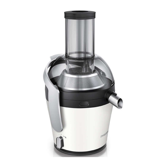
Juicer - easy to clean easy to use
Safety information
- This product meets the requirements regarding
interference suppression on radio and TV.
- After the product has been repaired, it should function
properly and has to meet the safety requirements as
officially laid down at this moment.
DISASSEMBLY- AND RE-ASSEMBLY ADVICE
- No specific issues
OPTIONAL (accessories)
- No specific issues
Published by Philips Consumer Lifestyle
12/03
- Voltage
- Frequency
- Type plate Wattage
- Cord length
- Dimensions:
Length
Width
Height
Weight
- Speeds
Printed in the Netherlands
HR1869/30
HR1869/35
: 220 V - 240 V
: 50 Hz - 60Hz
: 700 W
: 1 m
: 270 mm
: 245 mm
: 430 mm (incl. pusher)
: 4300 g
: 1 - 7500 rpm
2 - 10000 rpm
© Copyright reserved
Juicer
Version A
Subject to modification
Advertisement
Table of Contents

Related Manuals for Philips HR1869/30


Summary of Contents for Philips HR1869/30
- Page 1 DISASSEMBLY- AND RE-ASSEMBLY ADVICE - Speeds : 1 - 7500 rpm 2 - 10000 rpm - No specific issues OPTIONAL (accessories) - No specific issues Published by Philips Consumer Lifestyle Printed in the Netherlands © Copyright reserved Subject to modification 12/03...
- Page 2 TECHNICAL INFORMATION HR1869/30 HR1869/35 Used materials: - Housing : ABS - Bottom : PP - Feet base : PA 6.6 - Feet insert : EPDM rubber - Speed knob Base Knob : ABS Knob cover : SAN - Tray body...
- Page 3 HR1869/30 PARTSLIST - 3D VIEW (CRP‘s) HR1869/35 Service code Description 4203 035 96721 Pusher 4203 035 96731 4203 035 96741 Juice collector with spout 4203 035 96751 Integrated pulp container 4203 035 96761 Spout accessory 4203 035 96771 Detachable spout with drip stop...
- Page 4 3D VIEW FOR REPAIR HR1869/30 HR1869/35...
- Page 5 HR1869/30 PARTSLIST HR1869/35 Service code Description 4203 035 96801 Driving shaft 4203 035 98851 Main housing + motor crussion and stopper 4203 035 96821 Rubber ring 4203 035 96831 Bottom incl. Current limiter 4203 035 96841 Anti slip ring 4203 035 96851...
- Page 6 REPAIR INSTRUCTION HR1869/30 HR1869/35 1. Remove the Bottom First you have to remove the anti slip ring. Open all 4 screws (T15) to remove the Bottom. Anti slip ring 2. Change the driving shaft First you have to remove the bottom (see point 1.) Remove the cap, use a small screw driver.
- Page 7 REPAIR INSTRUCTION HR1869/30 HR1869/35 4. Remove the safety switch When you open both fl aps you can remove the safety switch. 5. Remove the locking arm Remove on each side the springs. Open the screw on both sides. Circuit diagram (without brake)
Need help?
Do you have a question about the HR1869/30 and is the answer not in the manual?
Questions and answers