Table of Contents
Advertisement
In the interests of user safety (Required by safety regulations in some countries) the set should be restored to its original
condition and only parts indentical to those specified should be used.
Important Service Safety Precaution ................................................................................................... 1-1
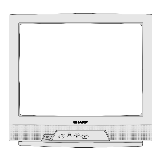
Location Of User's Control ...................................................................................................................... 2-1
Installation And Service Instructions ................................................................................................. 3-1
Service Mode ..................................................................................................................................................... 4-1
Adjustment Method ........................................................................................................................................ 5-1
Waveforms ......................................................................................................................................................... 6-1
Chassis Layout ................................................................................................................................................. 7-1
Block Diagram .................................................................................................................................................. 8-1
Description Of Schematic Diagram .......................................................................................................... 9-1
SCHEMATIC DIAGRAMS ......................................................................................................................................10-1
Printed Wiring Board Assemblies ........................................................................................................... 11-1
POWER INPUT............................AC 110-230 V, 50/60 Hz
POWER RATING .....................................................82W
PICTURE SIZE .............................1,239 cm
CONVERGENCE ............................................. Magnetic
SWEEP DEFLECTION .................................. .. Magnetic
FOCUS ........................................................ Electrostatic
INTERMEDIATE FREQUENCIES
Picture IF Carrier Frequency ...................... 45.75 MHz
Sound IF Carrier Frequency ...................... 41.25 MHz
Color Sub-Carrier Frequency ......................42.17 MHz
AUDIO POWER
OUTPUT RATING... ...................... 3.0 W(RMS) x 1pc
SHARP CORPORATION
SERVICE MANUAL
MODEL
CONTENTS
ELECTRICAL SPECIFICATIONS
SPEAKER
2
(192sq inch)
ANTENNA INPUT IMPEDANCE
TUNING RANGES
(Nominal)
COLOUR TELEVISION
Chassis No. GA4
Chassis No. GA6
21V-R70MM
SIZE ........................................................ 2" X 3.5", 1pc
VOICE COIL IMPEDANCE .................16 ohm at 400 Hz
VHF/UHF ........................................75 ohm Unbalanced
VHF-Channels ................................................. 2 thru 13
UHF-Channels ................................................14 thru 69
CATV Channels ............................................. 1 thru 125
(EIA, Channel Plan U.S.A.)
Specifications are subject to change without
prior notice.
This document has been published to be used for after
sales service only.
The contents are subject to change without notice.
21V-R70MM
S677421VR70MM
Page
Advertisement
Table of Contents

Subscribe to Our Youtube Channel
Related Manuals for Sharp 21v-r70MM


Summary of Contents for Sharp 21v-r70MM
-
Page 1: Service Manual
21V-R70MM SERVICE MANUAL S677421VR70MM COLOUR TELEVISION Chassis No. GA4 Chassis No. GA6 21V-R70MM MODEL In the interests of user safety (Required by safety regulations in some countries) the set should be restored to its original condition and only parts indentical to those specified should be used. -
Page 2: Important Service Safety Precaution
21V-R70MM CHAPTER 1. 21V-R70MM Service Manual 21V-R70MM Market IMPORTANT SERVICE SAFETY PRECAUTION IMPORTANT SERVICE SAFETY PRECAUTION Service work should be performed only by qualified service technicians who are thoroughly familiar with all safety checks and the servicing guidelines which follow:... -
Page 3: Schematic Diagrams
21V-R70MM IMPORTANT SERVICE SAFETY PRECAUTION (Continued) Connect the resistor connection to all exposed metal BEFORE RETURNING THE RECEIVER parts having a return to the chassis (antenna, metal (Fire & Shock Hazard) cabinet, screw heads, knobs and control shafts, escutcheon, etc.) and measure the AC voltage drop Before returning the receiver to the user, perform across the resistor. - Page 4 21V-R70MM CHAPTER 2. 21V-R70MM Service Manual 21V-R70MM Market LOCATION OF USER'S CONTROL [1] LOCATION OF USER'S CONTROL 2 – 1...
-
Page 5: Service Mode
21V-R70MM CHAPTER 3. 21V-R70MM Service Manual 21V-R70MM Market INSTALLATION AND SERVICE INSTRUCTIONS INSTALLATION AND SERVICE INSTRUCTIONS Note: (1) When performing any adjustments to resistor controls and transformers use non-metallic screwdrivers or TV alignment tools. (2) Before performing adjustments, the TV set must be on at least 15 minutes. - Page 6 21V-R70MM CHAPTER 4. 21V-R70MM Service Manual 21V-R70MM Market SERVICE MODE SERVICE MODE Service Mode Overview 1. Service mode is entered by SERVICE key input or CH-UP +VOL-DOWN input during reset. 2. Service mode is cleared by entering SERVICE key command during service mode.
- Page 7 21V-R70MM Adjustment Mode Items Item Name Register Range Default SUB-PICTURE 1 Chip CONTRAST 0~127 SUB-TINT 1 Chip TINT 0~127 SUB-COLOR 1 Chip COLOR 0~127 SUB-BRIGHT 1 Chip BRIGHT 0~255 SUB-SHARP 1 Chip VIDEO-TONE 0~63 V-SHIFT 1 Chip V-SHIFT H-SHIFT 1 Chip...
- Page 8 21V-R70MM SELF ADJUSTMENT H-VCO 1. When there is H-VCO self-adjustment key input for adjustment item H-VCO, self-adjustment is performed. 2. H-FREE(1chip) is set to 1. 3. H-OUT is set by intelligent monitor output. 4. IM input is set as TIM input.
- Page 9 21V-R70MM Setting Mode Items Item Name Register Range Default VIDEO TONE -GAIN (TV) 1 Chips V-TONE VIDEO TONE -GAIN (AV) 1 Chips V-TONE VIDEO TONE -GAIN (S-AV) 1 Chips V-TONE VIDEO TONE -GAIN(YUV) 1 Chips V-TONE ABCL 1 Chips ABCL...
- Page 10 21V-R70MM Setting Mode Items (Continued) Item Name Register Range Default FAO-VOL 0~63 CHARGE PUMP CC LEVEL MICON CC LEVEL OSD POS MICON OSD POS OFFSET-ADJ-COL 1 Chips COLOR -32~+32 OFFSET-ADJ-TINT 1 Chips TINT -32~+32 OFFSET-ADJ-TINT-YUV 1 Chips BASEBAND-TINT -32~+32 TIMER4-LOW SPEED...
- Page 11 21V-R70MM Option Mode Items OPTION FUNCTION Default Data DEMO Without DEMO With DEMO DOWNLOAD Without V-CHIP OP With V-CHIP OP V-CHIP Without V-CHIP With V-CHIP SPEAKER Without SPEAKER With SPEAKER Without FAO With FAO P.PREF Without P.REF With P.REF UNIV+...
-
Page 12: Adjustment Method
21V-R70MM CHAPTER 5. 21V-R70MM Service Manual 21V-R70MM Market ADJUSTMENT METHOD Memory Map Data C aution: to get into the s ervice mode, one of the ways is pres s direct key for s ervice items . There is three s tage of S ervice Mode data... - Page 13 21V-R70MM S econd S tage Default S etting Data S ervice Mode F unction R ange Data Data F 01 V -T ONE V IDE O -T O NE -G AIN (T V ) F 02 V -T ONE V IDE O -T O NE -G AIN (AV )
- Page 14 21V-R70MM F 65 R -C UT(OF F S E T) -63~+63 R -C UT -Y UV F 66 G -C UT(OF F S E T) -63~+63 G -C UT -Y UV F 67 B -C UT(OF F S E T)
- Page 15 21V-R70MM MO DE L NAME 21V -R 70MM ADJ US T ME NT O P T IO N S E T UP IT E M ADJ US T ME NT S T E P R ANG E R E F E R AS B E L O W...
- Page 16 21V-R70MM MO DE L NAME 21V -R 70MM ADJ US T ME NT B US S E T UP IT E M ADJ US T ME NT S T E P R ANG E R E F E R AS B E L O W...
- Page 17 21V-R70MM MO DE L NAME 21V -R 70MM ADJ US T ME NT H-P OS IT ION IT E M ADJ US T ME NT V 07 S T E P R ANG E P O S IT IO N...
- Page 18 21V-R70MM MO DE L NAME 21V -R 70MM ADJ US T ME NT V -S IZE IT E M ADJ US T ME NT V 09 S T E P R ANG E P O S IT IO N I2C C O NT R O L...
- Page 19 21V-R70MM MO DE L NAME 21V -R 70MM ADJ US T ME NT V -P HA S E IT E M ADJ US T ME NT V 06 S T E P R ANG E P O S IT IO N...
- Page 20 21V-R70MM MO DE L NAME 21V -R 70MM ADJ US T ME NT C L OS E D C A P T ION S E T UP IT E M ADJ US T ME NT V 18 S T E P R ANG E...
- Page 21 21V-R70MM MO DE L NAME 21V -R 70MM ADJ US T ME NT H-V C O IT E M ADJ US T ME NT V 21 S T E P R ANG E 0 - 7 P O S IT IO N...
- Page 22 21V-R70MM MO DE L NAME 21V -R 70MM ADJ US T ME NT P IF -V C O IT E M ADJ US T ME NT V 10 S T E P R ANG E 0 - 63 P O S IT IO N...
- Page 23 21V-R70MM MO DE L NAME 21V -R 70MM ADJ US T ME NT R F -A G C IT E M ADJ US T ME NT V 08 S T E P R ANG E 0-127 P O S IT IO N...
- Page 24 21V-R70MM MO DE L NAME 21V -R 70MM ADJ US T ME NT S C R E E N IT E M ADJ US T ME NT V 11,V 12,V 13 S T E P R ANG E 0~255 P O S IT IO N...
- Page 25 21V-R70MM MO DE L NAME 21V -R 70MM ADJ US T ME NT WHIT E B A L A NC E IT E M ADJ US T ME NT V 14,V 15,V 11,V 12,V 13 S T E P R ANG E...
- Page 26 21V-R70MM MO DE L NAME 21V -R 70MM ADJ US T ME NT S UB -B R IG HT IT E M ADJ US T ME NT V 04 S T E P R ANG E 0-255 P O S IT IO N...
- Page 27 21V-R70MM MO DE L NAME 21V -R 70MM ADJ US T ME NT S UB -P IC T UR E IT E M ADJ US T ME NT V 01 S T E P R ANG E 0-127 P O S IT IO N...
- Page 28 21V-R70MM MO DE L NAME 21V -R 70MM ADJ US T ME NT S UB -T INT IT E M ADJ US T ME NT V 02 S T E P R ANG E 0-127 P O S IT IO N...
- Page 29 21V-R70MM MO DE L NAME 21V -R 70MM ADJ US T ME NT S UB -C OL OR IT E M ADJ US T ME NT V 03 S T E P R ANG E 0-127 P O S IT IO N...
- Page 30 21V-R70MM MO DE L NAME 21V -R 70MM ADJ US T ME NT X -R A Y P R OT E C T ION OP E R A T ING C ONF IR MA T ION IT E M ADJ US T ME NT...
- Page 31 21V-R70MM MO DE L NAME 21V -R 70MM ADJ US T ME NT HIG H V OL T A G E IT E M ADJ US T ME NT S T E P R ANG E P O S IT IO N...
-
Page 32: Waveforms
21V-R70MM CHAPTER 6. 21V-R70MM Service Manual 21V-R70MM Market WAVEFORMS WAVEFORMS (1) 0.984 Vp-p (2) 5.36 Vp-p (3) 4.72 Vp-p (4) 4.98 Vp-p (5) 6.4 Vp-p Horiz. Rate Horiz. Rate Horiz. Rate Horiz. Rate Horiz. Rate (6) 1.84 Vp-p (7) 5.88. Vp-p (8) 1.72 Vp-p... -
Page 33: Chassis Layout
21V-R70MM CHAPTER 7. 21V-R70MM Service Manual 21V-R70MM Market CHASSIS LAYOUT CHASSIS LAYOUT 7 – 1... -
Page 34: Block Diagram
21V-R70MM CHAPTER 8. 21V-R70MM Service Manual 21V-R70MM Market BLOCK DIAGRAM MAIN BLOCK DIAGRAM 8 – 1... - Page 35 21V-R70MM 8 – 2...
- Page 36 21V-R70MM CRT BLOCK DIAGRAM 8 – 3...
-
Page 37: Description Of Schematic Diagram
21V-R70MM CHAPTER 9. 21V-R70MM Service Manual 21V-R70MM Market DESCRIPTION OF SCHEMATIC DIAGRAM DESCRIPTION OF SCHEMATIC DIAGRAM WAVEFORM MEASUREMENT CONDITIONS: NOTES: Photographs taken on a standard gated color bar 1. The unit of resistance "ohm" is omitted. signal, the tint setting adjusted for proper color. The (K=k Ω... - Page 38 21V-R70MM CHAPTER 10. 21V-R70MM Service Manual 21V-R70MM Market SCHEMATIC DIAGRAM SCHEMATIC DIAGRAM : MAIN UNIT 10 – 1...
- Page 39 21V-R70MM 10 – 2...
- Page 40 21V-R70MM SCHEMATIC DIAGRAM : CRT UNIT 10 – 3...
-
Page 41: Printed Wiring Board Assemblies
21V-R70MM CHAPTER 11. 21V-R70MM Service Manual 21V-R70MM Market PRINTED WIRING BOARD ASSEMBLIES 11 – 1... - Page 42 21V-R70MM 11 – 2...
- Page 43 21V-R70MM 11 – 3...
-
Page 44: Parts Guide
21V-R70MM PartsGuide PARTS GUIDE NO. S677421VR70MM No. XXXXXXXXXXXX XXXXXXXX 21V-R70M 21V- MODEL CONTENTS PICTURE TUBE MISCELLANEOUS PARTS PRINTED WIRING BOARD SUPPLIED ACCESSORIES ASSEMBLIES CABINET PARTS MAIN UNIT PACKING PARTS CRT UNIT INDEX Parts marked with " " are important for maintaining the safety of the set. Be sure to replace these parts with specified ones for maintaining the safety and performance of the set. - Page 45 21V-R70MM PRICE PARTS CODE PART DESCRIPTION RANK MARK DELIVERY [1] PICTURE TUBE RCILGA115WJN1 Degaussing Coil SEMI-ITC CRT VB540ADAC1S1E Grounding Strap QEARC2107PEZZ Purity Magnet PMAGF3046CEZZ [2] PRINTED WIRING BOARD ASSEMBLIES MAIN Unit ( PWB-A ) DUNTKD373WEA5 CRT Unit ( PWB-B )
- Page 46 21V-R70MM PRICE PARTS CODE PART DESCRIPTION RANK MARK DELIVERY [3] MAIN UNIT L751 Coil , CiLP0179CE RCILP0179CEZZ+ L801 Peaking , 10mH VP-DF100K0000Y L802 Peaking , 10mH VP-DF100K0000Y L803 Peaking , 10mH VP-DF100K0000Y L804 Peaking , 15mH VP-XF150K0000Y L806 Peaking , 10mH...
- Page 47 21V-R70MM PRICE PARTS CODE PART DESCRIPTION RANK MARK DELIVERY [3] MAIN UNIT C819 22p 50V Ceramic VCCCCY1HH220JY C820 0.47 50V Electrolytic VCEA9M1HW474M+ C821 0.015 50V Ceramic VCKYCY1HF153ZY C822 1 50V Electrolytic VCE9GA1HW105M+ C823 0.1 25V Ceramic VCKYCY1EF104ZY C824 330 16V Electrolytic...
- Page 48 21V-R70MM PRICE PARTS CODE PART DESCRIPTION RANK MARK DELIVERY [3] MAIN UNIT R524 10K 1/8W Carbon VRD-RA2BE103JY R525 1.2K 1/8W Carbon VRD-RA2BE122JY R526 100 1/8W Carbon VRD-RA2BE101JY R601 68 1/2W Carbon VRD-RM2HD680JY R602 39K 1/8W Carbon VRD-RA2BE393JY R603 22K 1/8W Carbon...
- Page 49 21V-R70MM PRICE PARTS CODE PART DESCRIPTION RANK MARK DELIVERY [3] MAIN UNIT R1023 270 1/16W Metal Oxide VRS-CY1JF271JY R1024 100 1/16W Metal Oxide VRS-CY1JF101JY R1027 100K 1/16W Metal Oxide VRS-CY1JF104JY R1031 100 1/8W Carbon VRD-RA2BE101JY R1032 10K 1/16W Metal Oxide...
- Page 50 21V-R70MM PRICE PARTS CODE PART DESCRIPTION RANK MARK DELIVERY [4] CRT UNIT C880 1000p 3kV Ceramic RC-KZ0153CEZZ C893 33 16V Electrolytic VCEA0A1CW336M+ R849 270 1/8W Carbon VRD-RA2BE271JY R850 47 1/8W Carbon VRD-RA2BE470JY R851 47 1/8W Carbon VRD-RA2BE470JY R852 47 1/8W Carbon...
- Page 51 21V-R70MM [7] CABINET PARTS PRICE PARTS CODE DESCRIPTION PART RANK MARK DELIVELY [7] CABINET PARTS Front Cabinet Ass'y CCABAB162WEV0 Front Cabinet Not Available Sharp Badge HBDGB0206PJSA R/C Cover HDECQ0316PJOT JBTNP0120PJSA Power Button MSPRC0005PEFW Power Button Spring JBTNC0106PJSB CTRL Button CTRL Button...
- Page 52 21V-R70MM [8] PACKING PARTS POLYETHYLENE BAG OPERATION MANUAL BATTERIES ANTENNA UNIT R/C UNIT HOSO PP PACKING FOAM PACKING CASE USE 2 TAPES TO FIX THE PACKING CASE CASE LABEL BARCODE LABEL MARK : NON REPLACEMENT ITEMS...
- Page 53 21V-R70MM PRICE PARTS CODE PART DESCRIPTION RANK MARK DELIVELY [8] PACKING PARTS Packing Case SPAKCD666WJZZ Bar Code Label TLABKA008WJZZ Packing Foam SPAKXB620WJZZ HOSO PP SPAKPA771WJZZ Case Label TLABZB837WJZZ...
- Page 54 21V-R70MM INDEX PRICE PART PRICE PART PARTS CODE PARTS CODE RANK MARK RANK RANK MARK RANK RH-DX0247CEZZ 3-D752 [ C ] RH-DX0302CEZZ 3-D391 CCABAB162WEV0 RH-DX0441CEZZY 3-D505 CCABBA681WEV0 RH-DX0476CEZZ 3-D701 [ D ] RH-DXA044WJZZ 3-D751 DUNTKA599WE01 RH-EX0263TAZZY 3-D810 DUNTKD373WEA5 " 3-D811 [ H ] "...
- Page 55 21V-R70MM PRICE PART PRICE PART PARTS CODE PARTS CODE RANK MARK RANK RANK MARK RANK " 3-C837 VCQYTA1HM104J+ 3-C1081 " 3-C843 VCQYTA1HM222J+ 3-C710 " 3-C1012 VCQYTA1HM563J+ 3-C601 VCEA0A1HW106M+ 3-C206 VHD1SS244//-1Y 3-D602 VCEA0A1HW107M+ 3-C505 VHDHSS4148+-1Y 3-D203 VCEA0A1HW335M+ 3-C312 " 3-D601 VCEA0A1HW474M+ 3-C305 "...
- Page 56 21V-R70MM PRICE PART PRICE PART PARTS CODE PARTS CODE RANK MARK RANK RANK MARK RANK " 4-R850 " 3-R1047 " 4-R851 " 3-R1049 " 4-R852 VRS-CY1JF221JY 3-R207 " 4-R864 " 3-R220 VRD-RA2BE472JY 3-R827 " 3-R833 " 3-R829 " 3-R1072 VRD-RA2BE473JY 3-R604 "...
- Page 57 EndPage © COPYRIGHT 2007 BY SHARP CORPORATION COPYRIGHT XXXX BYSHARP CORPORATION ALL RIGHTS RESERVED. No part of this publication may be reproduced, stored in a retrieval system, or transmitted in © COPYRIGHT XXXX BYSHARP CORPORATION any form or by any means, electronic, mechanical, photocopying, recording, or otherwise, without prior written permission of the publisher.
Need help?
Do you have a question about the 21v-r70MM and is the answer not in the manual?
Questions and answers