
Subscribe to Our Youtube Channel
Related Manuals for ARB 47L


Summary of Contents for ARB 47L
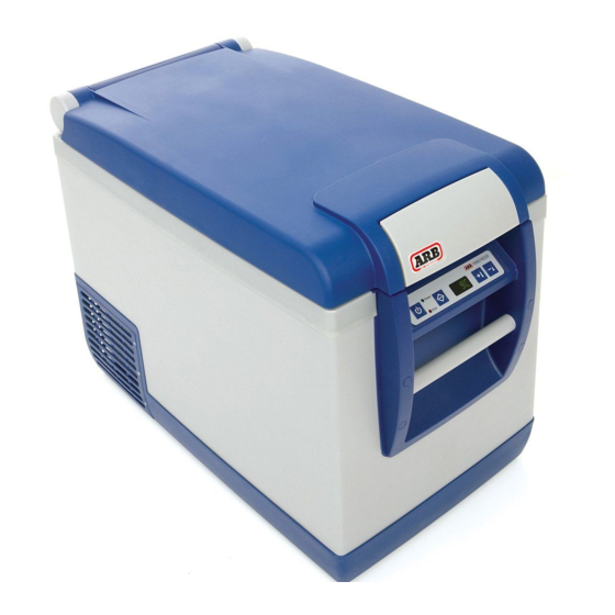
- Page 1 SERVICE MANUAL Model 47L(50 qrt) 35L(37 qrt) 60L(63 qrt) 78L(82 qrt) Type 10800010 10800020 10800030 10800040 Date December 2014...
-
Page 2: Table Of Contents
General information..........................2 How to use this manual ........................... 2 Contact information ..........................2 WARRANTY ..................................3 ARB Fridge Freezer Limited Warranty ....................3 Warranty procedure for service agents ....................4 Warranty Approval Form ......................... 5 STANDARD SERVICE/WARRANTY TIMES ........................6 SPARE PARTS .................................. -
Page 3: Introduction
1 INTRODUCTION 1.1 General information This manual is for the sole use of ARB approved repairers and provides information on servicing the ARB Fridge Freezer (types 10800010, 10800020, 10800030, 10800040). The part numbers covered by this manual include 10800XX1, 10800XX2, 10800XX3, 10800XX4, 10800XX5, 10800XX6 and 10800XX7 where XX represents the applicable fridge volume in litres eg 35, 47, 60 or 78. -
Page 4: Warranty
It is the responsibility of the owner to deliver and pick up the appliance from the place of service. ARB reserves the right to change the warranty conditions at any time by public notice and by attaching a clear change of warranty terms and conditions notice to the product visible at time of purchase. No party other than ARB Corporation Ltd is authorised to change the terms or conditions of this warranty. -
Page 5: Warranty Procedure For Service Agents
NOTE: A copy of the purchase receipt must be submitted with the claim. 5. ARB will assess the claim and if approved will dispatch the required parts as soon as practical at no charge to the repairer. If the claim is not approved, ARB will contact the repairer. ARB will also issue the repairer with a Warrant Claim Number and provide any special instructions for repair or return of faulty parts. -
Page 6: Warranty Approval Form
ARB Fridge Freezer 2.3 Warranty Approval Form (ARB Use Only) Claim FRIDGE FREEZER Authorised By: Number Service Contact: Agent: Address: Phone: Fax: Date In: Date Out: Job No: CUSTOMER DETAILS Name: Phone: Address: MOB: P/Code Cust Signature: *NOTE – Pre Warranty Inspection to be completed by customer prior to initiating claim (refer Warranty & Service booklet) -
Page 7: Standard Service/Warranty Times
The table above list warranty times for the service of individual components. If a single item is serviced or replaced and the warranty time is less than 0.5 hours, ARB will accept a total warranty time of 0.5 hours. This will allow for assessment and administration of the warranty claim. -
Page 8: Spare Parts
The part number given is for singular units unless otherwise stated in the item description. Drawings are indicative only, product appearance may change slightly. 123456 indicates "use to depletion" product, check stock with your ARB store. Revision Date – 22/12/2014 page 7... -
Page 9: Spare Parts Exploded Drawing
The following items are not illustrated in section 4.2. Item Description Part Number DC Plug adaptor - Red collar 10910030 Label - lid instructions 10910031 Instruction Manual 10910032 Fuse AC 100-240V T2 4 10910033 Fuse DC ceramic 12/24V T8A 32V (see section 12.) 10910034 Fuse DC Glass 12/24V 15Amp type 3AGA Clear Protective Cover... -
Page 10: Minimum Stocked Spare Parts
Minimum stocked spare parts ARB recommends that the following parts be stocked by all ARB fridge freezer service agents. As these parts are consumed, they should be replaced as soon as possible to ensure that all items are on hand when required. -
Page 11: Tools Required
The following tools will be required to perform specific non-refrigeration based servicing of the fridge Check vehicle wiring (refer to section 8.1) DC Voltage Drop tester (available from ARB – part # 10910040) Remove front or rear handle assembly (refer to sections and 9.9) -
Page 12: Troubleshooting
Check the vehicle wiring is adequate. - For cable lengths up to 6m (20’), ARB recommends a minimum automotive cable size of 6 mm (4.5 mm - For cable lengths greater than 6m (20’), ARB recommends that you consult a qualified technician for advice on the correct wire size. -
Page 13: Dc Power Supply
TROUBLESHOOTING 6.2 DC Power Supply Symptom Possible Cause(s) Suggested Action(s) No power to fridge when Interior light globe has blown. Replace light globe (refer to section 9.10). using a 12/24V DC power supply. 12/24V DC plug fuse has Replace 12/24V DC plug fuse (refer to Interior light does not work. - Page 14 Fault within main wiring loom. Test continuity of wiring loom from main circuit board to control panel circuit board. If fault identified and unrepairable, contact ARB for advice. Faulty compressor. Test compressor (refer to section 8.5). If compressor is faulty, contact a licensed refrigeration mechanic for assistance.
- Page 15 TROUBLESHOOTING DC Power Supply (continued) Symptom Possible Cause(s) Suggested Action(s) 12/24V DC fridge lead plug Fault within 12/24V DC fridge Check continuity of lead from plug to fuse blows repeatedly. power lead. socket. Replace lead if faulty or damaged. Incorrect fuse used in plug. Install the correctly rated fuse.
- Page 16 TROUBLESHOOTING DC Power Supply (continued) Symptom Possible Cause(s) Suggested Action(s) Fridge runs but digital Faulty control panel circuit Test with new control panel circuit board display is not visible. board. (refer to section 9.1). If symptom resolved, replace circuit board. Fridge runs but cannot Faulty control panel circuit Test with new control panel circuit board...
-
Page 17: Ac Power Supply
TROUBLESHOOTING 6.3 AC Power Supply Symptom Possible Cause(s) Suggested Action(s) No power to fridge when Poor connection of plug to Check that plug is correctly installed into using a 100-240V AC power back of fridge. the socket in back of fridge. supply. -
Page 18: Cooling
TROUBLESHOOTING 6.4 Cooling Symptom Possible Cause(s) Suggested Action(s) Fridge does not cool. Poor ventilation. Check that there is sufficient clearance Compressor run. around the fridge and that the fan is not obstructed. Compressor starts and stops Check that the correct battery protection because the battery setting is selected (refer section 6.6). - Page 19 TROUBLESHOOTING Cooling (continued) Symptom Possible Cause(s) Suggested Action(s) Temperature display is not Time lag has not been Allow the fridge to reach the set accurate with cabinet allowed for. temperature and cycle a few times before temperature. assessing accuracy of temperature. NOTE: A display temperature within 2- 3°C (3.6-5.4°F) of the actual temperature at the base of the...
- Page 20 TROUBLESHOOTING Cooling (continued) Symptom Possible Cause(s) Suggested Action(s) Fridge cools but Poor ventilation. Check that there is sufficient clearance compressor runs around the fridge and that the fan is not continuously. obstructed. Fridge is operating at or near The thermal capacity of the system is the thermal capacity of 50°C (122°F) below ambient temperature.
-
Page 21: General
TROUBLESHOOTING 6.5 General Symptom Possible Cause(s) Suggested Action(s) Lid is hard to release from The hinge assembly has Carefully remove the lid from the body of body of fridge. become contaminated with the fridge. dirt. Remove any dirt or grit from the hinge sockets and service the hinge assembly (refer to sections 9.20... -
Page 22: Battery Protection Settings
TROUBLESHOOTING 6.6 Battery Protection Settings The ARB Fridge Freezer is fitted with a battery monitor to control the level of discharge of the supply battery. The battery monitor has three settings; HIGH, MEDIUM and LOW. When set to HIGH, the battery monitor will provide maximum protection for the battery against excessive discharging. -
Page 23: Fault Finding Flow Charts
Refer to TEST COMPRESSOR CONTROL UNIT Refer to IS THE REPLACE CONTROL UNIT COMPRESSOR reassemble, test unit and return to customer CONTROL UNIT Refer to FAULTY? FRIDGE DOES NOT RUN Contact ARB for technical advise Revision Date – 22/12/2014 page 22... -
Page 24: Fridge Will Not Run On 12/24V Dc Power
COMPRESSOR RUNS REPLACE COMPRESSOR COMPRESSOR DOES NOT RUN REPLACE COMPRESSOR install new compressor control unit, Contact a licensed refrigeration Contact ARB for technical advice Contact a licensed refrigeration mechanic reassemble, test unit and return to mechanic for assistance. for assistance customer NOTE: THIS IS EXTREMELY UNLIKELY Revision Date –... -
Page 25: Checks And Tests
To check the vehicle wiring system, ARB recommend using a voltage drop tester. The voltage drop tester will simulate the start-up conditions of the Danfoss Compressor. These voltage drop testers are available from ARB and have been specifically built to simulate the running of an ARB Fridge Freezer (all models). - Page 26 NOTE: ARB recommend that a dedicated wiring circuit be used to connect the fridge directly to the battery via a suitable fuse. Refer to the wiring advice below Press the red button on the voltage drop tester and hold for no longer than 10 seconds.
- Page 27 Calculate the voltage drop by using the formula below. VOLTAGE VOLTAGE VOLTAGE ‘A’ ‘B’ DROP If the voltage drop is greater than 0.5 V in a 12V DC system, significant voltage drop is present within the circuit while the fridge is running. TEST OUTCOMES –...
-
Page 28: Test Compressor Control Unit - 12/24V Dc
7V DC. ARB recommends that the supply voltage be applied through the DC power socket in the back of the fridge and not directly to the control unit. - Page 29 Connect between terminals “T” and the lower terminal “C” using a short length of wire as shown. “C” NOTE: The connecting wire should be terminated with either push-on “T” connectors or spring loaded clips suitable for connection to the terminals. CAUTION: Make sure that there are no short circuits between the terminals and Connection...
-
Page 30: Test Main Circuit Board - 100-240V Ac
8.3 Test main circuit board – 100-240V AC WARNING: This test should only be performed by a licensed electrician. Purpose: To verify that the AC power section of the main circuit board is functioning correctly. Procedure: See below. Disconnect all power leads from the back of the Main circuit board fridge. - Page 31 Output “L” Using an AC voltmeter, check that the same AC voltage is measured between the live “L” and neutral “N” terminals on the output side of the main circuit board as shown. Output “N” NOTE: The main circuit board has been removed from the fridge for clarity only.
-
Page 32: Test Compressor Control Unit - 100-240V Ac
8.4 Test compressor control unit – 100-240V AC WARNING: This test should only be performed by a licensed electrician. Purpose: To verify the correct operation of the AC power section of the compressor control unit. Procedure: See below. Disconnect all power leads from the back of the fridge. - Page 33 Using a DC voltmeter, check that approximately 12V DC is measured between terminals “A” and upper “C” on the compressor control unit. NOTE: The voltage measurement may vary depending on the sensitivity of the DC “A” volt meter. Upper “C” TEST PASS –...
-
Page 34: Test Compressor
8.5 Test compressor Purpose: To verify that the internal compressor windings are functioning correctly. Procedure: See below. Disconnect all power leads from the back of the fridge. Remove the rear cover (refer to section 9.2). Remove the compressor control unit (refer to section 9.3). -
Page 35: Test Thermistor
8.6 Test thermistor Purpose: To verify that the thermistor is operating correctly. Procedure: Refer to section to identify if the fridge has a serviceable thermistor. For fridges with serviceable thermistors Disconnect all power leads from the back of the Disconnect fridge. - Page 36 Disconnect the thermistor connector plug from the control panel circuit board. NOTE: The control panel assembly has been removed for clarity only. There is no need to remove the control panel assembly to conduct this test. Thermistor loom Using an ohm meter (Ω), measure the resistance value of the thermistor.
-
Page 37: Adjust Internal Temperature Correlation
8.7 Adjust internal temperature correlation Purpose: To adjust the internal temperature calibration so that the display temperature matches the temperature at the base of the fridge. This adjustment should only be necessary if the thermistor has been replaced. NOTE : A display temperature within 2-3°C (3.6-5.4°F) of the actual temperature at the base of the fridge is within normal on/off cycle temperature variation. -
Page 38: Service
The touch pad decal is an integral sealing component used to reduce water ingress around the electronic control panel. The touch pad is a single use item only. ARB recommends removing and replacing a damaged touch pad to maintain sealing integrity. - Page 39 Disconnect the main wiring loom from the control panel circuit board. Disconnect the thermistor loom from the control panel circuit board. NOTE: For fridges manufactured after January 2014, the thermistor loom connects directly to the main PCB and not the display PCB as described above.
-
Page 40: Rear Cover - Remove And Refit
9.2 Rear Cover – Remove and Refit To remove rear cover Rear cover Disconnect all power leads from the back of the fridge. Remove the 12 screws that connect the rear cover to the body of the fridge. 3 screws per side 6 screws in base Pull the rear cover away from the body of the... -
Page 41: Compressor Control Unit - Replace
Remove 1 screw that connects the control unit to the compressor. Remove 1 screw For 35L and 47L models only Remove 6 screws as shown to release the compressor mounting base from the underside of the fridge. IMPORTANT: Support the compressor mounting base so that it does not drop more than 10 mm below the base of the fridge. - Page 42 ‘-’ – BLACK (DC Socket) Reposition compressor mounting base and fasten ‘+’ – WHITE (DC socket) using the original 6 screws (35L and 47L only). – YELLOW (lower PCB) – RED Refit the rear cover. (Fan) ‘F’ – BLACK (Fan) ‘A’...
-
Page 43: Main Circuit Board - Replace
9.4 Main circuit board - Replace Disconnect all power leads from the back of the Main circuit board fridge. Remove the rear cover (refer to section 9.2). Locate the main circuit board and disconnect all 6 connectors. NOTE: The main circuit board and corresponding connectors were changed in January 2014. - Page 44 MAIN PCB – January 2014 on CN2 - ‘OUTPUT’ CN1 - ‘INPUT’ To compressor From AC socket control unit Thermistor CN11 CN8 – ‘COMP’ ‘LAMP’ From compressor To light control unit CN9 – ‘DISPLAY’ To control panel CN10 circuit board To light switch Revision Date –...
-
Page 45: Rear Cover - Replace
9.5 Rear Cover – Replace Replace rear cover – to remove. Disconnect all power leads from the back of the fridge. Remove the rear cover (refer to section 9.2). CAUTION: Take care not to damage electrical wires or terminals. Disconnect the main circuit board from rear cover Main circuit board (refer to section 9.4). - Page 46 Remove the AC power socket cover. AC power socket cover Power panel with Remove the decal label for the power panel. decal removed Remove the 12/24V DC socket. Withdraw the AC socket socket (complete with leads) through the hole in the rear cover as shown.
- Page 47 Replace rear cover – to refit Fit the 12/24V DC and 100-240V AC sockets AC socket (complete with leads) to the new rear cover. DC socket fuse holder locating NOTE: Make sure that the fuse holder in the boss AC socket is at the top as shown. NOTE: Make sure that the locating boss in the DC socket faces the outer edge of the fridge as shown.
-
Page 48: Cooling Fan - Replace
NOTE: The fridge has been rotated for photo only. ARB does not recommend placing the fridge on its end as shown. Remove 10 screws Lower the compressor mounting base just enough to allow access to the fan mounting screws. - Page 49 Remove and retain the 4 rubber washers from the fan. HINT: A knife may be required to remove the rubber washers from the fan housing. Remove 4 rubber washers Fit the rubber washers between the new fan and Condenser the condenser as shown. Install the new fan and fasten to the condenser using the original 4 screws.
-
Page 50: Latch Assembly- Replace
9.7 Latch assembly- Replace Open the lid. Remove 3 screws as shown. HINT: On early latches, the centre screw can be accessed through the hole in the pivot as shown. Remove 3 screws Remove the latch assembly. Position the new latch assembly into the recess as shown. -
Page 51: Front Handle Assembly - Remove And Refit
9.8 Front handle assembly - Remove and Refit Disconnect all power leads from the back of the fridge. Remove latch assembly (refer to section 9.7). Remove control panel (refer to section 9.1). Remove and discard all 6 screw cover plugs using the following steps. - Page 52 Remove the front handle assembly from the body of the fridge. Front handle assembly 20 mm long Fit the new handle assembly to the body of the screws fridge using the original 6 screws. The 2 screws that fasten the top of the assembly are only 20 mm long.
-
Page 53: Rear Handle Assembly - Remove And Refit
9.9 Rear handle assembly – Remove and Refit Remove the lid. Remove hinge Remove and retain both hinge sockets and sockets screws (refer to section 9.21), Remove and discard all 6 screw cover plugs using the following steps. NOTE: Removing the plugs by any other means may result in damage to the handle assembly. - Page 54 Fit new screw cover plugs into the rear handle assembly. Each hole has a unique plug as shown. Plugs for 47L & 78L models are identified by a single letter. Plugs for 35L and 60L models are identified by a number.
-
Page 55: Light Globe - Replace
9.10 Light globe - Replace Disconnect all power leads from the back of the fridge. Position the basket to provide access to the light housing. This may require removing the basket. Remove the transparent light housing from internal case of the fridge. HINT: Place your finger under the lip of the light housing and ease it away from the internal case of the fridge. -
Page 56: Light Housing - Replace
9.11 Light housing - Replace Disconnect all power leads from the back of the fridge. Position basket to provide access to the light housing. This may require removing the basket. Remove the transparent light housing from internal case of the fridge. HINT: Place your finger under the lip of the light housing and ease it away from the internal case of the fridge. -
Page 57: Plug Fuse (12/24V Dc)- Replace
9.12 Plug fuse (12/24V DC)- Replace Disconnect the 12/24V DC power lead from the all power supplies. If fitted, remove the plastic adaptor collar from the end of the plug To do this, twist the collar and then pull it from the plug. Remove the single screw that fastest the plug together. -
Page 58: Device Fuse (100-240V Ac) - Replace
9.13 Device fuse (100-240V AC) - Replace Remove the AC and DC power leads from the power sockets. Remove the fuse insert from the rear panel of the fridge as shown. HINT: A small flat blade screwdriver may be required to help pry the insert away from its housing. -
Page 59: Dc Power Socket - Replace
9.14 DC power socket - Replace Disconnect all power leads from the back of the fridge. Remove the rear cover (refer to section 9.2). Remove the decal label from the power panel. Withdraw the socket (complete with leads) through the hole in the rear cover as shown. HINT: Use a flat blade screw driver to depress the tabs on the back of the socket. -
Page 60: Ac Power Socket - Replace
9.15 AC power socket - Replace Disconnect all power leads from the back of the fridge. Remove the rear cover (refer to section 9.2). Remove the AC socket protector. Withdraw the socket (complete with leads) through the hole in the rear cover as shown. HINT: Use a flat blade screw driver to depress the tabs on the back of the socket Disconnect the 3 wires from the back of the AC... -
Page 61: Rubber Feet - Remove And Refit
9.16 Rubber feet – Remove and Refit Remove 1 M6 bolt from the centre of the rubber foot using a 5 mm hex key. Remove M6 bolt Remove the rubber foot from the recess in the base of the fridge. Install the new rubber foot into the recess in the base of the fridge. -
Page 62: Compressor Mounting Feet - Replace
9.17 Compressor mounting feet – Replace To Remove compressor mounting feet Disconnect all power leads from the back of the fridge. Remove the rear cover (refer to section 9.2). Remove the retaining clip by sliding it sideways off the pin. HINT: A flat blade screwdriver may be useful to help remove the retaining clip. - Page 63 To refit compressor mounting feet Locate the rubber bush between the steel compressor base and the mounting base as shown. NOTE: The small end of the rubber bush should locate within the steel base of the compressor. Compressor base Rubber bush Mounting Pin Compressor base...
-
Page 64: Compressor Mounting Base - Replace
Remove the 10 screws that attach the compressor mounting base to the body of the fridge. NOTE: The fridge has been rotated for photo only. ARB does not recommend placing the fridge on its end as shown. Remove 10 screws Lower the compressor mounting base (complete with compressor and condenser) from the base of the fridge. - Page 65 Remove the compressor mounting base the from Remove 2 fridge. rubber feet Remove 2 rubber feet from compressor mounting base. Retain both the rubber feet and the fastening bolts. Discard old compressor mounting base. Fit the 2 rubber feet to the new compressor mounting base using the original fasteners.
-
Page 66: Lid Seal - Remove And Refit
9.19 Lid seal – Remove and Refit Lid seal - To Remove Locate and mark the join in the lid seal as shown. Mark join in seal Using a pair of long nosed pliers, grip the seal and pull it away from the lid. Remove seal Lid seal - To Refit... -
Page 67: Lid Hinge Assembly- Service
9.20 Lid hinge assembly- Service Remove the lid from the body of the fridge Remove 2 screws Remove 2 screws as shown. Remove the washer, hinge pin and hinge spring. HINT: Depress the hinge pin slightly and then release to dislodge the washer and eject the hinge. -
Page 68: Cabinet Hinge Assembly- Service
9.21 Cabinet hinge assembly- Service Remove one screw from the centre of the hinge socket as shown. Remove the hinge socket by sliding it towards the front of the fridge as shown. Insert the new hinge socket into the rear handle assembly as shown. -
Page 69: Thermistor - Replace
9.22 Thermistor – Replace Fridge with non-serviceable thermistors The thermistor is non-servicable on 47L fridges with serial numbers up to and including those listed in the table below. Please contact ARB for service advice for these fridges. Part Number Country... - Page 70 Place a mark on the thermistor wire where it exits the fridge cabinet as shown. Mark thermistor wire Withdraw the thermistor wire and thermistor from the fridge cabinet. Remove thermistor Disconnect the 2-pin connector from the end of the thermistor wire where it joins the main wiring Disconnect loom.
- Page 71 Apply thermal heat transfer paste to the metallic end of the thermistor as shown. This paste is available from Jaycar (p/n NM-2012) Apply heat transfer paste Insert the new thermistor into the hole in the fridge cabinet. Continue to insert the thermistor wire until the mark made in the previous step lines up with the body of the fridge.
-
Page 72: Improving Performance With Am Radios
9.23 Improving performance with AM radios The fitment of a braided wire (ARB p/n 10900023) can assist with AM radio clarity whilst the fridge compressor is running. To install this wire, please follow the instillation procedure below. Disconnect all power leads from the back of the fridge. - Page 73 Fit the supplied 2-way connector to terminal “-” on the compressor control unit. Existing black wire Connect the black wire and connector removed in the previous step to the 2-way connector. Connect the blade terminal on the braided wire to the second terminal on the 2-way connector.
-
Page 74: Basket Retention
9.24 Basket retention The basket on the 78L (82 qrt) fridge is fixed to the inside of the fridge cabinet via a ‘P” clip and stainless steel screw. The basket divider is fixed to the basket with a plastic tie. Both of these features are required for regulatory compliance and must not be removed. -
Page 75: Service By Refrigeration Mechanic
10 SERVICE BY REFRIGERATION MECHANIC 10.1 Compressor recharge information The ARB fridge freezer range as designated in this manual use refrigerant R134a. Model 47L(50 qrt) 35L(37 qrt) 60L(63 qrt) 78L(82 qrt) Type 10800010 10800020 10800030 10800040 R134a g/(oz) 47/(1.66) 42/(1.48) 56/(1.98) -
Page 76: Wiring
11 WIRING 11.1 Wiring diagram- Model ARB 35, 47, 60 & 78L Fridge Freezer Type : 10800010/20/30/40 Manufactured prior to January 2014 Revision Date – 17/08/2014 page 75... - Page 77 Model : ARB 35, 47, 60 & 78L Fridge Freezer Type : 10800010/20/30/40 Manufactured after January 2014 Revision Date – 17/08/2014 page 76...
-
Page 78: Wiring Schematic
11.2 Wiring schematic Model : ARB 35, 47, 60 & 78L Fridge Freezer Type : 10800010/20/30/40 Manufactured prior to January 2014 Revision Date – 17/08/2014 page 77... -
Page 79: Product Improvement Change Log
12 PRODUCT IMPROVEMENT CHANGE LOG The following table contains the serial number breakpoints for specific product changes by fridge type. NOTE: At the time of publication, no product improvements have been made to models 10800XX6 or 10800XX7. This is because both models were introduced after the most recent product improvement was implemented. - Page 80 47L Type 10800010 Model 10800471 10800472 10800473 10800474 10800475 United South England/Middle Australia Europe States Africa East Production Date Revised latch May-09 Serial Number 07001602 Production Date 21/09/09 08/09/09 29/10/09 Serviceable thermistor Jul-09 Serial Number 07002740 0700451 08000473 07000161 Production Date Aluminum plate over evaporator –...
- Page 81 60L Type 10800030 Model 10800351 10800352 10800353 10800354 10800355 United England/Middle Australia Europe South Africa States East Production Date 22/01/2013 26/01/2013 14/03/2013 28/05/2013 2/07/2013 Revised hinge spring Jan-2013 Serial Number 11005071 11000317 11000041 11000287 11000060 Replace steel rivets with Production Date 7/02/2012 8/03/2012 17/01/2012...
-
Page 82: Definition Of Change
LED better suits the customer needs in all lighting conditions. The new white LED circuit board is backward compatible with all ARB fridges. Note: do NOT use the green LED on 35, 60 or 78L fridge models. -
Page 83: Superseded Products
New ARB eded ARB compatible with compatible with Part No Part No. ARB Description New P/N Old P/N SPRING KIT - LID HINGE 35/47L 10910051 10920001 10910052 10920023 SPRING KIT - LID HINGE 60/78L 10910053 10920002 SOCKET KIT - LID HINGE...
Need help?
Do you have a question about the 47L and is the answer not in the manual?
Questions and answers