Table of Contents
Advertisement
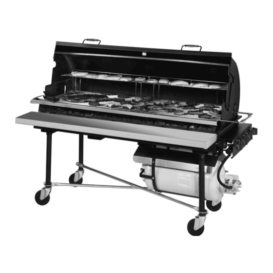
PORTA-GRILL
ASSEMBLY, OPERATING & MAINTENANCE INSTRUCTIONS
THIS UNIT HAS BEEN CERTIFIED BY ITS/WARNOCK HERSEY
TO MEET ANSI Z83.11, CGA 1.8-1994, AGA REQUIREMENT 13-90
AND CAN/CGA-1.6-M88
BELSON
OUTDOORS, INC.
111 NORTH RIVER ROAD, PO BOX 207
NORTH AURORA, IL 60542-0207
TELEPHONE:
630-897-8489
TOLL FREE: 1-800-323-5664
BY BELSON
FOR OUTDOOR USE ONLY
II
Advertisement
Table of Contents

Subscribe to Our Youtube Channel
Related Manuals for Belson PORTA-GRILL II

Summary of Contents for Belson PORTA-GRILL II
- Page 1 PORTA-GRILL BY BELSON ASSEMBLY, OPERATING & MAINTENANCE INSTRUCTIONS THIS UNIT HAS BEEN CERTIFIED BY ITS/WARNOCK HERSEY TO MEET ANSI Z83.11, CGA 1.8-1994, AGA REQUIREMENT 13-90 AND CAN/CGA-1.6-M88 FOR OUTDOOR USE ONLY BELSON OUTDOORS, INC. 111 NORTH RIVER ROAD, PO BOX 207...
-
Page 2: Table Of Contents
TABLE OF CONTENTS PAGE SAFETY --------------------------------------------------------------- GETTING STARTED -------------------------------------------- SAFETY PRACTICES TO AVOID PERSONAL INJURY ----------------------------------- PROPANE TANK STORAGE, HANDLING AND FILLING -------------------------------------- CONNECTING AND DISCONNECTING YOUR TANK --------------------------------------------------------- LEAK CHECK ------------------------------------------------------ LIGHTING INSTRUCTIONS ------------------------------------ VIII IGNITOR AND BURNER ADJUSTMENTS ------------------ 8, 9 CARE AND MAINTENANCE ------------------------------------ 10, 11... -
Page 3: Isafety
SAFETY Dear Customer: PLEASE read this manual carefully and follow the recommendations enclosed. This will help assure you of the most enjoyable and trouble-free operation of your new PORTA-GRILL . Keep this manual for future reference. FOR YOUR SAFETY If you smell gas: 1. -
Page 4: Getting Started
When the unit is not in use, the supply L.P. gas cylinder valve must be turned off and all control valves on panel must be turned to the 'OFF' position. The regulator and hose assembly equipped with the unit must be used at all times. Replace- ment of such assembly must be supplied by BELSON OUTDOORS, INC. -
Page 5: Safety Practices To Avoid Personal Injury
SAFETY PRACTICES TO AVOID PERSONAL INJURY -Don'ts- DON’T move your grill while it is in operation or still hot. DON'T use an open flame when testing for gas leaks. DON'T use charcoal briquettes, wood chips or any flammable material on top or in place of lava rock. -
Page 6: Propane Tank Storage, Handling And Filling
PROPANE TANK STORAGE, HANDLING AND FILLING Propane gas should be handled and stored with care. We suggest asking your propane gas dealer, when having your tank filled, for a short course in handling, care, and storage of propane gas tanks.Most dealers will be glad to instruct you on how to store and handle your tank. -
Page 7: Vconnecting And Disconnecting Your Tank
Slide tank into support hoops and fasten to orientation bracket with (4) 3/8”-16 x 3/4” hex head bolts. The Belson fuel tank will only draw vapor fumes while lying in the horizontal position as shown on the drawing. Never attempt to use the Belson LP fuel tank in the vertical position or outside of its support hoops. -
Page 8: Leak Check
LEAK CHECK BEFORE LIGHTING YOUR GRILL: Turn your L.P. gas supply on and test all fittings for leaks, before attempting to light grill, be certain all control valves are in the 'OFF' position. Slowly turn the gas supply on (leaving control valves in the 'OFF' position) and check all connections with a solution of 50% liquid soap, 50% water. -
Page 9: Lighting Instructions
LIGHTING INSTRUCTIONS IMPORTANT: Before each use of your grill, inspect the gas hose prior to turning the gas 'ON' If there is evidence of cuts, wear, or abrasion, it must be replaced prior to use. Contact Customer Service 1-800-323-5664 for replacement parts. Do not use the unit if the odor of gas is present. -
Page 10: Ignitor And Burner Adjustments
VIII IGNITOR AND BURNER ADJUSTMENTS IGNITOR/ELECTRODE ADJUSTMENT The electrode inside the fire box is fixed and checked at the factory for optimum spark. The tip is 1/8” from the inside surface of the burner tube. In the event that the ceramic insulator should crack and need replacement, it is easily removed by loosening the mounting screw. - Page 11 FLAME ADJUSTMENT Each grill burner is tested and adjusted at the factory prior to shipment; however, variations in the local gas supply or a conversion from one gas to another may make it necessary to adjust the burners. Flames should be blue and stable with no yellow tips, excessive noise or lifting. If any of these conditions exist, check if the air shutter or burner ports are blocked by dirt, debris, spider webs, etc.
-
Page 12: Care And Maintenance
CARE AND MAINTENANCE Caution: Avoid steam burns by not using a wet sponge or cloth to clean the grill while it is hot. Some cleaners produce noxious fumes or can ignite if applied to a hot surface. Be sure all grill controls are turned off and the grill is cool before using any type of aerosol cleaner on or around the grill. - Page 13 SPIDERS AND INSECTS: The burner venturi area is narrow, dark and protected making the burners extremely attractive to spiders. A nesting spider is capable of spinning a web overnight that could block gas and air flow. This is a very dangerous condition which can cause a fire to occur behind the valve panel, thereby damaging the grill and making it unsafe to operate.
-
Page 14: Xassembly Instructions
ASSEMBLY INSTRUCTIONS PORTA-GRILL PG-2460-II Unpacking shipping package and set all components seperately aside. Place the firebox (1) upside down on a shipping cardboard on ground. Thread all 4 legs (2) into pre-weleded sockets at fire box. (Legs with locking device on one side, see Assembly Diagram) Install tank support hoops (3) using (4) 3/8-16 x 3/4”... - Page 15 ASSEMBLY DIAGRAM MODEL: PORTA-GRILL PG-2460-II...
-
Page 16: Hardware List
HARDWARE LIST QTY DESCRIPTION 3/8" - 16 X 3/4" BOLT 3/8" - 16 X 1" BOLT 1/4" - 20 X 3/4" FLAT HEAD SCREW 1/4" - 20 X 1/2" ROUND HEAD SLOTTED MACHINE SCREW 1/4" - 20 HEX NUT 3/8" - 16 HEX SERRATED-FLANGE NUT BREAD BOX HOOD PG-200 (optional) Install grill support brackets using (4) 3/8"-16x1"... -
Page 17: Part List
PART LIST PG-2460-II PART LIST ITEM NUMBER PART NUMBER QTY/FIX DESCRIPTION PG-II-FB FIRE BOX PG-INST2 INSTRUMENT PANEL PI-BNRBRKT2 BURNER SUPPORT BRACKETS PI-PGIIBNR BURNER TUBES – STAINLESS STEEL PI-GRLSPT GRILL GRATE SUPPORTS PG-IILRG LAVA ROCK GRATES PG-2460G NICKEL PLATED COOKING GRATE PG-200 BREAD-BOX HOOD PI-PBCSTR... - Page 18 PART LIST DIAGRAM PG-2460-II PG-200 (optional) PG-XBRACE (optional)
-
Page 19: Trouble Shooting
TROUBLE SHOOTING 1. PROBLEM: Burner flame does not extend full length of burner. CAUSE: Burner holes are plugged or restricted with dirt and grease. SOLUTION: Remove foreign matter from burner holes. 2. PROBLEM: Yellow flame -- low heat. CAUSE: Improper air mixture. SOLUTION: Adjust air mixer cover to obtain a blue flame. -
Page 20: Warranty
XIII WARRANTY Belson Policies We at Belson take extreme care to ensure that your shipment arrives in acceptable condition. When your shipment arrives, the carrier will provide you with a delivery receipt. It is vital that you count the number of pieces being delivered and inspect for damages prior to signing this document.
Need help?
Do you have a question about the PORTA-GRILL II and is the answer not in the manual?
Questions and answers