
Related Manuals for Flexit SPIRIT UNI 3


Summary of Contents for Flexit SPIRIT UNI 3
-
Page 1: Installation Manual
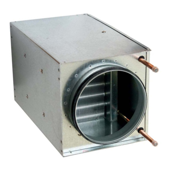
110869E-08 2015-06 ART. NO.: 110863 110948 FLEXIT SPIRIT Installation manual Water heating element... -
Page 2: Table Of Contents
3.6 Frost sensor (B5) 3.7 DIP switch Maintenance Appendix 1 To obtain correct values, employ the Flexit calculation application available at our home page www.fl exit.no Our products are subject to continuous development and we therefore reserve the right to make changes. -
Page 3: Uni
UNI 4 Water heating element art.no. 110948 has the highest Air flow rate: 470 m capacity of Flexit’s water heating elements. It is designed Power consumption: 1,72kW for systems with air flow rates of more than 280 m3/h, and Temperature, °C... -
Page 4: Capacity And Sound Data, Supply Air Side, Uni
Water heating element installation manual Capacity and sound data, supply air side, UNI 3 Air flow rate [l/s] Yellow fi eld: SFP < 1.0 per fan Fig. 2 100% 100% 80dB (A) 75dB (A) 70dB (A) 65dB (A) 60dB (A) Air flow rate [m ³... -
Page 5: Plumbing
Water heating element installation manual 2 Plumbing All plumbing must be carried out by an authorised plumber. 2.2 Location of the water heating element Place the unit near a gully to prevent damage in case of a water leakage. NB! Please consider service accessibility before commencing installation. -
Page 6: Connections
Water heating element installation manual 2.4 Venting 2.3 Connections Remember to connect the T piece for venting, at the highest Employ the recommended connections (se Fig. 6) unless point in the circuit. otherwise stated. 2.5 Frost risk A spring loaded shutting damper must be connected to Fig. -
Page 7: Electrical Work
Water heating element installation manual Electrical work Uni 3-4 Connect the new cable to the central unit. Remove the cover for the electrical room. Place the sensor in the supply air duct (refer to label on top of the ventilation unit), approximately 1m away from the the heating element. -
Page 8: Frost Sensor (B5)
Water heating element installation manual 3.2 Frost sensor (B5) 4 Maintenance The lamellas in the heating element must be cleaned on WARNING! To prevent the element from fre- a regular basis. First, clean the entry side of the element ezing, a sensor (B5) must be attached to the with a brush, then the whole element can be cleaned with water pipe for outgoing water. - Page 12 Flexit AS, Televeien 15, N-1870 Ørje www.flexit.com...
Need help?
Do you have a question about the SPIRIT UNI 3 and is the answer not in the manual?
Questions and answers