Table of Contents
Advertisement
TABLE OF CONTENTS
1 Safety Precautions----------------------------------------------- 3
2 Specifications ----------------------------------------------------- 5
2.1. WH-SD24AE WH-UD24AE ----------------------------- 5
2.2. WH-SD28AE WH-UD28AE ----------------------------- 7
3 Features ------------------------------------------------------------- 9
4 Location of Controls and Components ------------------10
4.1. Indoor Unit--------------------------------------------------10
4.2. Outdoor Unit -----------------------------------------------12
5 Dimensions--------------------------------------------------------13
5.1. Indoor Unit--------------------------------------------------13
5.2. Outdoor Unit -----------------------------------------------14
6 Refrigeration And Water Cycle Diagram-----------------15
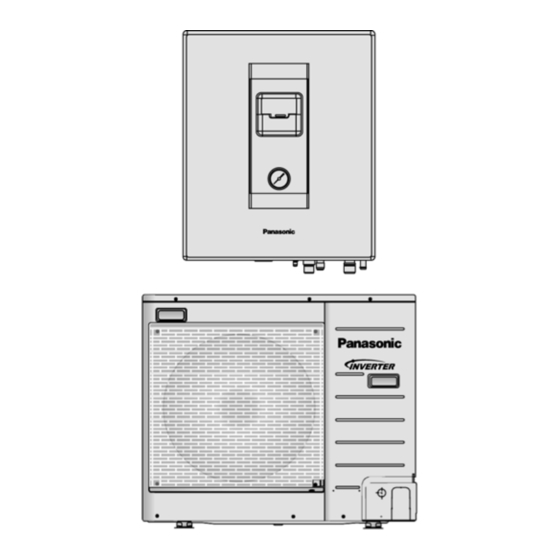
Indoor Unit
WH-SD24AE WH-UD24AE
WH-SD28AE WH-UD28AE
PAGE
7 Block Diagram --------------------------------------------------- 16
8 Wiring Connection Diagram--------------------------------- 17
8.1. Indoor Unit ------------------------------------------------- 17
8.2. Outdoor Unit----------------------------------------------- 18
9 Electronic Circuit Diagram----------------------------------- 19
9.1. Indoor Unit ------------------------------------------------- 19
9.2. Outdoor Unit----------------------------------------------- 20
10 Printed Circuit Board ------------------------------------------ 21
10.1. Indoor Unit ------------------------------------------------- 21
10.2. Outdoor Unit----------------------------------------------- 22
11 Installation Instruction ---------------------------------------- 24
11.1. Select The Best Location ------------------------------ 24
© Panasonic HA Air-Conditioning (M) Sdn. Bhd. 2008.
Unauthorized copying and distribution is a violation of
law.
Order No. PHAAM0809001C2
Air-to-Water Heatpump
Outdoor Unit
PAGE
Advertisement
Table of Contents

Related Manuals for Panasonic WH-UD28AE


Summary of Contents for Panasonic WH-UD28AE
-
Page 1: Table Of Contents
10.2. Outdoor Unit----------------------------------------------- 22 5.2. Outdoor Unit -----------------------------------------------14 11 Installation Instruction ---------------------------------------- 24 6 Refrigeration And Water Cycle Diagram-----------------15 11.1. Select The Best Location ------------------------------ 24 © Panasonic HA Air-Conditioning (M) Sdn. Bhd. 2008. Unauthorized copying and distribution is a violation of law. - Page 2 Switch and Water Pump-------------------------------- 70 18 Technical Data---------------------------------------------------- 72 18.1. Operation Characteristics ------------------------------ 72 18.2. Heating Capacity Table --------------------------------- 76 18.3. Hydraulic Pump Performance------------------------- 76 19 Exploded View and Replacement Parts List ----------- 77 19.1. WH-SD24AE WH-SD28AE --------------------------- 77 19.2. WH-UD24AE WH-UD28AE --------------------------- 79...
-
Page 3: Safety Precautions
1 Safety Precautions • Read the following “SAFETY PRECAUTIONS” carefully before perform any servicing. • Electrical work must be installed or serviced by a licensed electrician. Be sure to use the correct rating and main circuit for the model installed. •... - Page 4 19. The unit is only for use in a closed water system. Utilization in an open water circuit may lead to excessive corrosion of the water piping. 20. Do not insert your fingers or other objects into the unit. 21. Do not dismantle refrigerant piping using pipe wrench. 22.
-
Page 5: Specifications
2 Specifications 2.1. WH-SD24AE WH-UD24AE Item Unit Outdoor Unit Performance Test Condition EUROVENT Heating Capacity 7.00 BTU/h 23900 kJ/h 25200 4.40 BTU/hW 15.0 Noise Level dB (A) Power Level dB Air Flow 54.5 (1924) l/min (ft /min) Refrigeration Control Device Expansion Valve Refrigeration Oil FV50S (800) - Page 6 Item Unit Power Cord Number of core Length m (ft) Thermostat Electronic Control Protection Device Electronic Control Item Unit Indoor Unit Performance Test Condition EUROVENT °C Operation Range Outdoor Ambient -20 ~ 24 °C Water Outlet 25 ~ 55 Noise Level dB (A) Power Level dB Dimension...
-
Page 7: Wh-Sd28Ae Wh-Ud28Ae
2.2. WH-SD28AE WH-UD28AE Item Unit Outdoor Unit Performance Test Condition EUROVENT Heating Capacity 9.00 BTU/h 30700 kJ/h 32400 4.10 BTU/hW 14.0 Noise Level dB (A) Power Level dB Air Flow 54.5 (1924) l/min (ft /min) Refrigeration Control Device Expansion Valve... - Page 8 Item Unit Indoor Unit Performance Test Condition EUROVENT °C Operation Range Outdoor Ambient -20 ~ 24 °C Water Outlet 25 ~ 55 Noise Level dB (A) Power Level dB Dimension Height mm (inch) 644 (25-11/32) Width mm (inch) 504 (19-27/32) Depth mm (inch) 295 (11-5/8)
-
Page 9: Features
3 Features • Inverter Technology - Energy saving • High Efficiency • Compact Design • Environment Protection - Non-ozone depletion substances refrigerant (R410A) • Long Installation Piping - Long piping up to 30 meter with height difference 20 meter - Flexible 4-way piping for outdoor unit •... -
Page 10: Location Of Controls And Components
4 Location of Controls and Components 4.1. Indoor Unit 4.1.1. Location of Control... -
Page 12: Outdoor Unit
4.1.2. Main Components 4.2. Outdoor Unit... -
Page 13: Dimensions
5 Dimensions 5.1. Indoor Unit... -
Page 14: Outdoor Unit
5.2. Outdoor Unit... -
Page 15: Refrigeration And Water Cycle Diagram
6 Refrigeration And Water Cycle Diagram Piping size Min. Max. Rated Common Additional Piping Piping Length Length Elevation Refrigerant Length Length Model Liquid (g/m) D24AE 5/8” 1/4” D28AE 5/8” 1/4” * If piping length is over common length, additional refrigerant should be added as shown in the table. -
Page 16: Block Diagram
7 Block Diagram... -
Page 17: Wiring Connection Diagram
8 Wiring Connection Diagram 8.1. Indoor Unit... -
Page 18: Outdoor Unit
8.2. Outdoor Unit... -
Page 19: Electronic Circuit Diagram
9 Electronic Circuit Diagram 9.1. Indoor Unit... -
Page 20: Outdoor Unit
9.2. Outdoor Unit... -
Page 21: Printed Circuit Board
10 Printed Circuit Board 10.1. Indoor Unit 10.1.1. Main Printed Circuit Board... -
Page 22: Outdoor Unit
10.2. Outdoor Unit 10.2.1. Main Printed Circuit Board... - Page 23 10.2.2. Capacitor Printed Circuit Board 10.2.3. Noise Filter Printed Circuit Board...
-
Page 24: Installation Instruction
11 Installation Instruction 11.1. Select The Best Location 11.2. Indoor/Outdoor Unit INDOOR UNIT Installation Diagram • There should not be any heat source or steam near the unit. • A place where air circulation in the room is good. • A place where drainage can be easily done. •... -
Page 25: Indoor Unit
11.3. Indoor Unit 11.3.3. INDOOR UNIT INSTALLATION 11.3.3.1. Install The Indoor Unit 11.3.1. HOW TO FIX INSTALLATION PLATE 1. Engage the slots on the indoor unit to the hooks of The mounting wall is strong and solid enough to prevent it from installation plate. - Page 26 • If non-brass metallic piping is used for installation, make sure to insulate the pipes to prevent galvanic corrosion. • Make sure to insulate the water circuit pipes to prevent reduction of heating capacity. • After installation, check the water leakage condition in connection area during test run.
- Page 27 • Secure the cable onto the control board with the holder 11.3.4.1. Wire Stripping and Connecting (clamper). Requirement 2. Cable connection to the power supply through isolating device (Disconnecting means). • Connect the approved polychloroprene sheathed power supply cable (3 x 4.0 mm ), type designation 60245 IEC 57 or heavier cord to the terminal board, and connect the other end of the cable to isolating device (Disconnecting...
-
Page 28: Outdoor Unit
11.4. Outdoor Unit 11.4.1. INSTALL THE OUTDOOR UNIT • After selecting the best location, start installation according to Indoor/Outdoor Unit Installation Diagram. 1. Fix the unit on concrete or rigid frame firmly and horizontally by bolt nut (ø10 mm). 2. When installing at roof, please consider strong wind and earthquake. - Page 29 11.4.3. EVACUATION OF THE EQUIPMENT WHEN INSTALLING AN AIR-TO-WATER HEATPUMP, BE SURE TO EVACUATE THE AIR INSIDE THE INDOOR UNIT AND PIPES in the following procedure. 1. Connect a charging hose with a push pin to the Low side of a charging set and the service port of the 3-way valve. •...
-
Page 30: Connect The Cable To The Outdoor Unit
11.4.4. CONNECT THE CABLE TO THE OUTDOOR UNIT (FOR DETAIL REFER TO WIRING DIAGRAM AT UNIT) 1. Remove the control board cover from the unit by loosening the screw. 2. Connecting cable between indoor unit and outdoor unit shall be approved polychloroprene sheathed 4 × 4.0 mm flexible cord, type designation 60245 IEC 57 or heavier cord. -
Page 31: Operation And Control
12 Operation and Control 12.1. Basic Function Inverter control, which equipped with a microcomputer in determining the most suitable operating mode as time passes, automatically adjusts output power for maximum comfort always. In order to achieve the suitable operating mode, the microcomputer maintains the set temperature by measuring the temperature of the environment and performing temperature shifting. -
Page 32: Water Pump
12.1.3. Setting Water Outlet Temperature For Heat Mode • The set temperature define the parameters for the Ambient (OD temp.) dependent operation of the unit. Where by the internal water setting temperature is determined automatically depending on the outdoor temperature. The colder outdoor temperatures will result in warmer water and vice verse. -
Page 33: Pump Down Operation
12.3. Pump Down Operation Purpose Ensure the pump down operation when relocating or disposing of the unit. The pump down operation will extract all refrigerant from the piping into the outdoor unit. 1. Press the pump down operation button to begin forced cooling operation. 2. -
Page 34: Protection Control
13 Protection Control 13.1. Protection Control For All Operations 13.1.1. Time Delay Safety Control 1. The compressor will not start for three minutes after stop of operation. 13.1.2. 30 Seconds Forced Operation 1. Once the compressor starts operation, it will not stop its operation for 30 seconds. 2. -
Page 35: Protection Control For Heating Operation
13.1.7. Low Frequency Protection Control 2 • When all the below conditions comply, the compressor frequency will change to lower frequency. Temperature, T, for: Heating Outlet water (°C) T < 14 or T Outdoor air (°C) T < 4 or T Indoor heat exchanger (°C) 13.1.8. -
Page 36: Servicing Mode
14 Servicing Mode 14.1. Test Run 1. Fill up the boiler tank with water. For details refer to boiler tanks installation instruction and operation instruction. 2. Set ON to the indoor unit and RCCB. Then, for control panel’s operation please refers to air-to-water heatpump’s operation instruction. -
Page 37: Maintenance Guide
15 Maintenance Guide In order to ensure optimal performance of the unit, checks and inspections on the unit and the field wiring must be carried out regularly. Please request a licensed technician for carry out maintenance job. Before carried out any maintenance or repair work, and removing the front plate of heat exchanger unit, always switch off all power supply (i.e. - Page 38 6. How to release the trapped air in water circuit • Turn up the level to become horizontal. (Refer to figure “Pressure relief valve”). The trapped air will be drained out together with water. After few seconds, turn down the level to stop the water drainage. •...
-
Page 39: Troubleshooting Guide
16 Troubleshooting Guide 16.1. Refrigeration Cycle System In order to diagnose malfunctions, make sure that there are no electrical problems before inspecting the refrigeration cycle. Such problems include insufficient insulation, problem with the power source, malfunction of a compressor and a fan. The normal pressure of the refrigeration cycle depends on various conditions, the standard values for them are shown in the table on the right. -
Page 40: Relationship Between The Condition Of The Air-To-Water Heatpump Indoor And Outdoor Units And Pressure And Electric Current
16.2. Relationship Between The Condition Of The Air-to-Water Heatpump Indoor And Outdoor Units And Pressure And Electric Current Heating Mode Condition of the Air-to-Water Heatpump indoor and outdoor Low Pressure High Pressure Electric current during operation units Insufficient refrigerant (gas leakage) Clogged capillary tube or Strainer Heat radiation deficiency of the outdoor unit... -
Page 41: Breakdown Self Diagnosis Function
16.3. Breakdown Self Diagnosis Function 16.3.1. Self Diagnosis Function (Three Digits Alphanumeric Code) • Once abnormality has occurred during operation, the unit will stop its operation, operation LED blink and system error display show the error code. • Although operation LED and system error display goes off when power supply is turned off, if the unit is operated under a breakdown condition, the operation LED and system error display will light up again. -
Page 42: Error Codes Table
16.4. Error Codes Table Diagnosis display Abnormality / Protection control Abnormality Judgement Primary location to verify No abnormality detected — — Indoor / outdoor abnormal > 1 min after starting operation • Internal / external cable connections communication • Indoor / Outdoor PCB Indoor water outlet temperature sensor Continue for 5 sec. -
Page 43: Self-Diagnosis Method
16.5. Self-diagnosis Method 16.5.1. Indoor/Outdoor Abnormal Communication (H11) Malfunction Decision Conditions: During standby and operation of heating, the data received from outdoor unit in indoor unit signal transmission is checked whether it is normal. Malfunction Caused: 1. Faulty outdoor unit PCB. 2. - Page 44 To determine if outdoor PCB or indoor PCB is faulty: 1. Start with outdoor terminal first. 2. Remove terminal 3 wire. 3. Measure with a multimeter (voltage in DC range). 4. If it is never constant, outdoor PCB is good fluctuating in between 20-70Vdc, outdoor PCB is in good condition. 16.5.2.
- Page 45 16.5.3. Compressor Temperature Sensor Abnormality (H15) Malfunction Decision Conditions: During startup and operation of heating, the temperatures detected by the compressor temperature sensor are used to determine sensor error. Malfunction Caused: 1. Faulty connector connection. 2. Faulty sensor. 3. Faulty PCB. Abnormality Judgment: Continue for 5 seconds.
- Page 46 16.5.4. Outdoor Current Transformer Open Circuit (H16) Malfunction Decision Conditions: A current transformer (CT) is detected by checking the compressor running frequency ( rated frequency) and CT detected input current (less than 0.65A) for continuously 20 seconds. Malfunction Caused: 1. CT defective. 2.
- Page 47 16.5.5. Indoor Refrigerant Liquid Temperature Sensor Abnormality (H23) Malfunction Decision Conditions: During startup and operation of heating, the temperatures detected by the indoor refrigerant liquid temperature sensor are used to determine sensor error. Malfunction Caused: 1. Faulty connector connection. 2. Faulty sensor. 3.
- Page 48 16.5.6. Outdoor Air Temperature Sensor Abnormality (H27) Malfunction Decision Conditions: During startup and operation of heating, the temperatures detected by the outdoor air temperature sensor are used to determine sensor error. Malfunction Caused: 1. Faulty connector connection. 2. Faulty sensor. 3.
- Page 49 16.5.7. Outdoor Pipe Temperature Sensor Abnormality (H28) Malfunction Decision Conditions: During startup and operation of heating, the temperatures detected by the outdoor pipe temperature sensor are used to determine sensor error. Malfunction Caused: 1. Faulty connector connection. 2. Faulty sensor. 3.
- Page 50 16.5.8. Outdoor Discharge Pipe Temperature Sensor Abnormality (H30) Malfunction Decision Conditions: During startup and operation of heating, the temperatures detected by the outdoor discharge pipe temperature sensor are used to determine sensor error. Malfunction Caused: 1. Faulty connector connection. 2. Faulty sensor. 3.
- Page 51 16.5.9. Unspecified Voltage between Indoor and Outdoor (H33) Malfunction Decision Conditions: The supply power is detected for its requirement by the indoor/outdoor transmission. Malfunction Caused: 1. Wrong models interconnected. 2. Wrong indoor unit and outdoor unit PCBs used. 3. Indoor unit or outdoor unit PCB defective.
- Page 52 16.5.10. Water Flow Switch Abnormality (H62) Malfunction Decision Conditions: During operation of heating, the water flow detected by the indoor water flow switch is used to determine water flow error. Malfunction Caused: 1. Water leak in system. 2. Faulty connector connection. 3.
- Page 53 16.5.11. Outdoor Low Pressure Abnormality (H63) Malfunction Decision Conditions: During operation of heating, the outdoor low pressure sensor output signal is 0Vdc or 5Vdc. Malfunction Caused: 1. Faulty connector connection. 2. Faulty sensor. 3. Faulty PCB. Abnormality Judgment: Continue for 5 seconds (but no judgment for 5 minutes after compressor startup/restart).
- Page 54 16.5.12. Outdoor High Pressure Abnormality (H64) Malfunction Decision Conditions: During operation of heating, the outdoor high pressure sensor output signal is 0Vdc or 5Vdc. Malfunction Caused: 1. Faulty connector connection. 2. Faulty sensor. 3. Faulty PCB. Abnormality Judgment: Continue for 5 seconds (but no judgment for 5 minutes after compressor startup/restart).
- Page 55 16.5.13. Indoor-Control Panel Communication Abnormality (H65) Malfunction Decision Conditions: During standby and operation of heating, indoor-control panel error occur. Malfunction Caused: 1. Faulty connector connection. 2. Faulty control panel. 3. Faulty PCB. Abnormality Judgment: Continue for 1 minute.
- Page 56 16.5.14. Compressor Low Pressure Protection (H66) Error code will not display (no OFF/ON Control Panel LED blinking) but store in EEPROM Malfunction Decision Conditions: During operation of heating, pressure 0.2 MPa and below is detected by the outdoor low pressure sensor. Malfunction Caused: 1.
- Page 57 16.5.15. Indoor Water Inlet Temperature Sensor Abnormality (H68) Malfunction Decision Conditions: During startup and operation of heating, the temperatures detected by the indoor water inlet temperature sensor are used to determine sensor error. Malfunction Caused: 1. Faulty connector connection. 2. Faulty sensor. 3.
- Page 58 16.5.16. Indoor High Pressure Protection (H98) Error code will not display (no TIMER LED blinking) but store in EEPROM Malfunction Decision Conditions: During operation of heating, pressure 4.0 MPa and above is detected by outdoor high pressure sensor. Malfunction Caused: 1.
- Page 59 16.5.17. Four Way Valve Abnormality (F11) Malfunction Decision Conditions: During operation of heating, temperature below 0°C is detected by indoor pipe temperature sensor. Malfunction Caused: 1. Connector in poor contact. 2. Faulty sensor. 3. Faulty outdoor unit PCB. 4. Four way valve defective. Abnormality Judgment: Continue 4 times in 30 minutes.
- Page 60 16.5.18. Power Factor Correction (PFC) Abnormality (F90) Malfunction Decision Conditions: During operation of heating, PFC protection circuitry at the outdoor unit main PCB senses abnormal high DC voltage level. Malfunction Caused: 1. DC voltage peak due to power supply surge. 2.
- Page 61 16.5.19. Refrigeration Cycle Abnormality (F91) Malfunction Decision Conditions: 1. During operation of heating, compressor frequency > Fhrated. 2. During operation of heating, running current: 0.65A < I < 1.65A. 3. During operation of heating, indoor pipe — water inlet < 5°C. Malfunction Caused: 1.
- Page 62 16.5.20. Compressor Rotation Failure (F93) Malfunction Decision Conditions: A compressor rotation failure is detected by checking the compressor running condition through the position detection circuit. Malfunction Caused: 1. Compressor terminal disconnect. 2. Outdoor PCB malfunction. Abnormality Judgment: Continue 4 times in 20 minutes.
- Page 63 16.5.21. IPM Overheating (F96) Malfunction Decision Conditions: During operation of heating, temperature 95°C is detected by the outdoor IPM temperature sensor. Malfunction Caused: 1. IPM overheat due to short circuit of hot discharge air flow. 2. IPM overheat due to defective of outdoor fan motor. 3.
- Page 64 16.5.22. Compressor Overheating (F97) Malfunction Decision Conditions: During operation of heating, temperature above 112°C is detected by the compressor tank temperature sensor. Malfunction Caused: 1. Refrigerant shortage (refrigerant leakage). 2. 2/3 way valve closed. 3. Detection error due to faulty compressor tank temperature sensor. Abnormality Judgment: Continue 4 times in 30 minutes.
- Page 65 16.5.23. Input Over Current Detection (F98) Malfunction Decision Conditions: During operation of heating, outdoor current above 19.0A is detected by the outdoor current transformer (CT). Malfunction Caused: 1. Over-current due to compressor failure. 2. Over-current due to defective outdoor unit PCB. 3.
- Page 66 16.5.24. Output Over Current Detection (F99) Malfunction Decision Conditions: During operation of heating, outdoor current above 30.0 ± 5.0 A is detected by the IPM DC Peak sensing circuitry. Malfunction Caused: 1. DC peak due to compressor failure. 2. DC peak due to defective power transistor(s). 3.
-
Page 67: Disassembly And Assembly Instructions
17 Disassembly and Assembly Instructions WARNING High Voltage are generated in the electrical parts area by the capacitor. Ensure that the capacitor has discharged sufficiently before proceeding with repair work. Failure to heed this caution may result in electric shocks. 17.1. -
Page 68: To Remove Pressure Gauge
17.3. To Remove Pressure Gauge 17.4. To Remove Control Panel... -
Page 69: To Remove Electronic Controller Board And Transformer
17.5. To Remove Electronic Controller Board and Transformer 17.6. To Remove RCCB... -
Page 70: To Remove Pressure Relief Valve, Flow Switch And Water Pump
17.7. To Remove Pressure Relief Valve, Flow Switch and Water Pump When reinstall the water pipe, use grease or water at the joining. When reinstall the water pipe, use grease or water at the joining. - Page 71 When reinstall the water pipe, use grease or water at the joining.
-
Page 72: Technical Data
18 Technical Data 18.1. Operation Characteristics 18.1.1. WH-SD24AE WH-UD24AE Heating Characteristics at Different Outdoor Air Temperature Condition Outdoor air temperature : 7°C (DBT), 6°C (WBT) Indoor water inlet temperature : 30°C Indoor water outlet temperature : 35°C Piping length : 7m... - Page 73 Heating Characteristics at Different Piping Length Condition Outdoor air temperature : 7°C (DBT), 6°C (WBT) Indoor water inlet temperature : 30°C Indoor water outlet temperature : 35°C Piping length : 7m...
- Page 74 18.1.2. WH-SD28AE WH-UD28AE Heating Characteristics at Different Outdoor Air Temperature Condition Outdoor air temperature : 7°C (DBT), 6°C (WBT) Indoor water inlet temperature : 30°C Indoor water outlet temperature : 35°C Piping length : 7m...
- Page 75 Heating Characteristics at Different Piping Length Condition Outdoor air temperature : 7°C (DBT), 6°C (WBT) Indoor water inlet temperature : 30°C Indoor water outlet temperature : 35°C Piping length : 7m...
-
Page 76: Heating Capacity Table
7.00 1.59 6.73 1.78 6.21 1.95 5.87 2.11 HC: Heating Capacity (kW) IP: Power Input (kW) LWC: Leaving Water Condenser Temperature (°C) Tamb: Ambient Temperature (°C) 18.2.2. WH-SD28AE WH-UD28AE Tamb 3.62 1.82 3.58 2.01 3.32 2.16 3.07 2.36 2.91 2.53 6.10... -
Page 77: Exploded View And Replacement Parts List
19 Exploded View and Replacement Parts List 19.1. WH-SD24AE WH-SD28AE Note: The above exploded view is for the purpose of parts disassembly and replacement. The non-numbered parts are not kept as standard service parts. - Page 78 <Model: WH-SD24AE WH-SD28AE> REF. NO. DESCRIPTION & NAME QTY. WH-SD24AE WH-SD28AE REMARKS ← BASE PAN CWD521235 ← HOT WATER COIL-COMPLETE CWB90C1017 ← TUBE CONNECTOR-COMPLETE CWT29C1035 ← FLARE NUT (1/4) CWT251063 ← FLARE NUT (5/8) CWT251064 ← FILTER CWB511006 ← PUMP CWB532075 ←...
-
Page 79: Wh-Ud24Ae Wh-Ud28Ae
19.2. WH-UD24AE WH-UD28AE... - Page 81 Note: The above exploded view is for the purpose of parts disassembly and replacement. The non-numbered parts are not kept as standard service parts.
- Page 82 <Model: WH-UD24AE, WH-UD28AE> REF. NO. DESCRIPTION & NAME QTY. WH-UD24AE WH-UD28AE REMARKS ← BASE PAN ASS’Y CWD52K1199 ← COMPRESSOR DC 280V 5KD240XAA21 ← BUSHING-COMPRESSOR MOUNT CWH50055 ← NUT FOR COMP. MOUNT. CWH561049 ← PACKING CWB811017 ← CONDENSER COMPLETE CWB32C2277 ←...
Need help?
Do you have a question about the WH-UD28AE and is the answer not in the manual?
Questions and answers