Table of Contents
Advertisement
This service information is designed for experienced repair technicians only and is not designed for use by the general public.
It does not contain warnings or cautions to advise non-technical individuals of potential dangers in attempting to service a product.
Products powered by electricity should be serviced or repaired only by experienced professional technicians. Any attempt to
service or repair the products dealt with in this service information by anyone else could result in serious injury or death.
In order to avoid frostbite, be assured of no refrigerant leakage during the installation or repairing of refrigerant circuit.
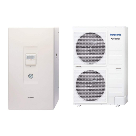
Indoor Unit
WH-SDC09F3E8
WH-SDC12F9E8
WH-SDC14F9E8
WH-SDC16F9E8
WARNING
PRECAUTION OF LOW TEMPERATURE
Order No: PAPAMY1405035CE
Outdoor Unit
WH-UD09FE8
WH-UD12FE8
WH-UD14FE8
WH-UD16FE8
Destination
Europe
© Panasonic Corporation 2014.
Advertisement
Table of Contents

Related Manuals for Panasonic WH-SDC09F3E8


Summary of Contents for Panasonic WH-SDC09F3E8
- Page 1 PRECAUTION OF LOW TEMPERATURE In order to avoid frostbite, be assured of no refrigerant leakage during the installation or repairing of refrigerant circuit. © Panasonic Corporation 2014.
-
Page 2: Safety Precautions
1. Safety Precautions Read the following “SAFETY PRECAUTIONS” carefully before perform any servicing. Electrical work must be installed or serviced by a licensed electrician. Be sure to use the correct rating and main circuit for the model installed. ... - Page 3 - Power Supply 1: Use approved 20A 4-poles circuit breaker with a minimum contact gap of 3.0 mm. - Power Supply 2: Use approved 15/16A 2-poles circuit breaker with a minimum contact gap of 3.0 mm. (Only applicable for WH-SDC09F3E8) Use approved 20A 4-poles circuit breaker with a minimum contact gap of 3.0 mm.
- Page 4 CAUTION 14. After installation, check the water leakage condition in connection area during test run. If leakage occur, it will cause damage to other properties. 15. The unit described in this manual is designed for use in a closed water system only. Utilization in an open water circuit may lead to excessive corrosion of the water piping.
- Page 5 WH-SDC12F9E8 WH-UD12FE8 Item Unit Outdoor Unit Performance Test Condition EN 14511 Condition A35W7 (Ambient/Water) 10.00 Cooling Capacity BTU/h 34100 kcal/h 8600 2.85 Cooling EER kcal/hW 2.45 Condition A7W35 A2W35 (Ambient/Water) 12.00 11.40 Heating Capacity BTU/h 41000 38900 kcal/h 10320 9800 4.74 3.44 Heating COP...
- Page 6 Item Unit Outdoor Unit ø Three Power Source (Phase, Voltage, Cycle) Condition A35W7 A7W35 A2W35 (Ambient/Water) Input Power Cooling: 3.51 Heating: 2.53 Heating: 3.31 Maximum Input Power For Heatpump System 5.85 Power Supply 1 : Phase (Ø) / Max. Current (A) / Max. Input Power (W) 3Ø...
- Page 7 Item Unit Indoor Unit Volume Expansion Vessel Capacity of Integrated Electric Heater 9.00 Note: Cooling capacities are based on outdoor air temperature of 35°C Dry Bulb with controlled indoor water inlet temperature of 12°C and water outlet temperature of 7°C. ...
- Page 8 3. Features Inverter Technology - Energy saving High Efficiency Environment Protection - Non-ozone depletion substances refrigerant (R410A) Long Installation Piping - Long piping up to 30 meter with height difference 20 meter - Flexible 4-way piping for outdoor unit ...
-
Page 9: Main Components
4.1.4 Main Components (Only applicable for WH- Control panel S**12/14/16*9E8) Pressure relief valve Cabinet front plate Flow switch Cabinet Pressure gauge Handle (2 pieces) Water pump Overload protector 1 phase RCCB/ELCB Connector name (4 pieces) (Only applicable for Water Outlet Heater assembly WH-S**09*3E8) Gas Refrigerant... -
Page 10: Indoor Unit
5. Dimensions Indoor Unit <Top View> <Front View> <Side View> 35 98 107 115 155 <Bottom View> 205.5 98.5 Relative position between the indoor unit and the installation plate <Front View> 213.5 213.5 140.7 140.7 Installation 306.4 Plate Indoor unit external dimensions line Unit: mm... - Page 11 Outdoor Unit <Top View> <Side view> <Front View> <Side View> 318.5 <Back view> Unit: mm...
-
Page 12: Refrigeration And Water Cycle Diagram
Additional Piping Piping Model Length Elevation Refrigerant Length Length Liquid (g/m) WH-SDC09F3E8 WH-UD09FE8 Ø15.88 mm Ø9.52 mm WH-SDC12F9E8 5 ~ 7.5 (5/8") (3/8") WH-UD12FE8 WH-SDC14/16F9E8 WH-UD14/16FE8 * If piping length is over common length, additional refrigerant should be added as shown in the table. - Page 13 8.1.2 WH-SDC12F9E8 WH-SDC14F9E8 WH-SDC16F9E8...
- Page 14 Outdoor Unit...
-
Page 15: How To Adjust Water Flow Rate [Service Mode: 02]
15.5 How to Adjust Water Flow Rate [SERVICE MODE: 02] Before adjust the water flow rate, make sure that the total water volume in the installation is 50 litres minimum for heating side. The default setting is SPEED 3 (Only for WH-S**09*3E8 and WH-S**09/12*9E8) and SPEED 4 for WH- S**14/16*9E8. - Page 16 19.1.2 WH-SDC12F9E8 WH-UD12FE8 Heating Characteristics at Different Outdoor Air Temperature Condition Outdoor air temperature : 7°C (DBT), 6°C (WBT) Indoor water inlet temperature : 30°C Indoor water outlet temperature : 35°C Piping length : 7 m 13.000 12.000 11.000 10.000 9.000 8.000 Outdoor Temperature (°C)
- Page 17 Cooling Characteristics at Different Outdoor Air Temperature Condition Outdoor air temperature : 35°C (DBT), -°C (WBT) Indoor water inlet temperature : 12°C Indoor water outlet temperature : 7°C Piping length : 7 m 12.500 11.500 10.500 9.500 8.500 7.500 Outdoor Temperature (°C) 5.500 4.500 3.500...
- Page 18 Cooling Characteristics at Different Outdoor Air Temperature Condition Outdoor air temperature : 35°C (DBT), -°C (WBT) Indoor water inlet temperature : 19°C Indoor water outlet temperature : 14°C Piping length : 7 m 16.000 15.000 14.000 13.000 12.000 11.000 Outdoor Temperature (°C) 5.500 4.500 3.500...
- Page 19 Cooling Characteristics at Different Outdoor Air Temperature Condition Outdoor air temperature : 35°C (DBT), -°C (WBT) Indoor water inlet temperature : 23°C Indoor water outlet temperature : 18°C Piping length : 7 m 12.000 11.000 10.000 9.000 8.000 7.000 Outdoor Temperature (°C) 5.500 4.500 3.500...
- Page 20 Heating Characteristics at Different Piping Length Condition Outdoor air temperature : 7°C (DBT), 6°C (WBT) Indoor water inlet temperature : 30°C Indoor water outlet temperature : 35°C Piping length : 7 m 12.500 12.000 11.500 11.000 10.500 10.000 Piping Length (m) 4.000 3.500 3.000...
- Page 21 Cooling Characteristics at Different Piping Length Condition Outdoor air temperature : 35°C (DBT), -°C (WBT) Indoor water inlet temperature : 12°C Indoor water outlet temperature : 7°C Piping length : 7 m 11.000 10.000 9.000 8.000 7.000 6.000 Piping Length (m) 3.800 3.700 3.600...
-
Page 22: Heating Capacity Table
19.2 Heating Capacity Table 19.2.1 WH-SDC09F3E8 WH-UD09FE8 Water Out (°C) Input Input Input Input Input Input Capacity Capacity Capacity Capacity Capacity Capacity Outdoor Air (°C) Power Power Power Power Power Power 8650 3060 8300 3210 7950 3410 7600 3610 7150... -
Page 23: Cooling Capacity Table
19.3 Cooling Capacity Table 19.3.1 WH-SDC09F3E8 WH-UD09FE8 Water In (°C) Water Out (°C) Outdoor Air (°C) Capacity (W) Input Power (W) Capacity (W) Input Power (W) Capacity (W) Input Power (W) 7500 1150 9100 1200 7000 1130 8350 1770 10900...
Need help?
Do you have a question about the WH-SDC09F3E8 and is the answer not in the manual?
Questions and answers