NAD M3 Service Manual
Hide thumbs
Also See for M3:
- Specification sheet (4 pages) ,
- Owner's manual (80 pages) ,
- Owner's manual (21 pages)
Table of Contents
Advertisement
Advertisement
Chapters
Table of Contents

Related Manuals for NAD M3


Summary of Contents for NAD M3
- Page 1 © NAD 2006 M3 C/AH NAD ELECTRONICS INTERNATIONAL Integrated Amplifier TORONTO...
- Page 2 CONTENTS SECTION 1 ..SUMMARY SECTION 2 ..CABINET & MAIN CHASSIS SECTION 3 ..ELECTRICAL SECTION 4 ..REPLACEMENT PARTS LIST...
-
Page 3: Table Of Contents
SECTION 1 SUMMARY CONTENTS PRODUCT SAFETY SERVICING GUIDELINES FOR AUDIO PRODUCTS ..... SERVICING PRECAUTIONS ................• General Servicing Precautions • Insulation Checking Prodedure • Electrostatically Sensitive Devices ALIGNMENT PROCEDURE ................1-4,5 • POWER DRIVEN VOLTAGE • IDLING CURRENT • BALANCE INPUTS CMRR SPECIFICATIONS ................... -
Page 4: Product Safety Servicing Guidelines For Audio Products
PRODUCT SAFETY SERVICING GUIDELINES FOR AUDIO PRODUCTS CAUTION : DO NOT ATTEMPT TO MODIFY THIS 5. NO LEAD OR COMPONENT SHOULD TOUCH A PRODUCT IN ANY WAY, NEVER PERFORM CUSTOM- RECIVING TUBE OR A RESISTOR RATED AT 1 WATT IZED INSTALLATIONS WITHOUT MANUFACTURER’S OR MORE. -
Page 5: Servicing Precautions
SERVICING PRECAUTIONS CAUTION Before servicing the Stereo amplifier covered by Electrostatically Sensitive (ES) Devices Some semiconductor (solid state) devices can be damaged this service data and its supplements and addends, read and follow the SAFETY PRECAUTIONS. NOTE: if unforeseen easily by static electricity. Such components commonly are circumstances create conflict between the following servicing called Electrostatically Sensitive (ES) Devices. -
Page 6: Alignment Procedure
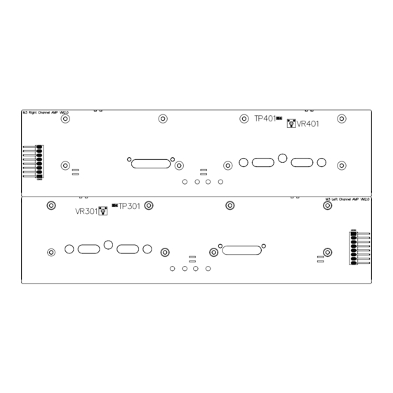
ALIGNMENT PROCEDURE A. POWER DRIVEN VOLTAGE(PSU BOARD) Connect a DC Millivoltmeter to TP601/TP701 1 and 2 pin, then adjust VR601/VR701(6.8kohms) for 0V±0.1V. B. IDLING CURRENT(AMP BOARD) 1.Connect a DC Millivoltmeter betweenTP301 2 pins, then adjust VR301 (200ohms) for 7-8mV reading on meter. 2.Connect a DC Millivoltmeter between TP401 2 pins, then adjust VR401 (200ohms) for 7-8mV reading on meter. -
Page 7: Balance Inputs Cmrr
C. BALANCE INPUTS CMRR 1.Volum set 0dB, Input 2V/10KHZ common mode sinwave signal at L channel Balance input,Connect a AC Millivoltmeter to preout1L then adjust R565 for lowest output level. 2. Volum set 0dB,Input 2V/10KHZ common mode sinwave signal at R channel Balance input,Connect a AC Millivoltmeter to preout1R then adjust R564 for lowest output level. -
Page 8: Specifications
SPECIFICATIONS NAD M3 INTEGRATE AMPLIFIER Note: Specifications are measured in accordance with EIA Standard RS-490 (IHF A-202) for amplifiers Power Amplifier Section 180W (17dBw) Continuous output power into 4/8 ohms (Minimum RMS power per channel, both channels driven, With no more than the rated distortion) Rated distortion (THD)(20Hz –20kHz) -
Page 9: Specifications 1
Signal-to-Noise ratio 110dB ref 500mV (A-weighted, line In, Pre-Out) Rated distortion (THD)(20Hz –21kHz) 0.005% Channel Separation 110dB (1kHz 2V Line/balanced IN, 2V Pre-Out) Input Sensitivity 320mV for 2V out Input Overload Line input Balanced input < Frequency response(5Hz-70KHz) +/-0.3dB THD (SUB OUT) 0.01% (2V CD in, 2V SUB out;... - Page 10 SECTION 2 CABINET & MAIN CHASSIS CONTENTS EXPLODED VIEWS ................. . 2 - 2 1.
-
Page 11: Exploded Views
EXPLODED VIEWS 1. Cabinet and main frame section S010 S016 C012 C011 PR06 R006 R009 R007 R008 R010 R011 T001 C013 S011 S009 R005 R004 C014 A006 S008 C018 C019 PR01 C004 S001 S013 C015 C024 S016 C023 PR02 S015 R003 C026 PR03... -
Page 12: Packing Accessory Section
2. Packing accessory section P015 P012 P013 P011 P014 P016 P010 P009 P008 P006 P005 P007 P004 P003 P002 P001... -
Page 13: Exploded View Parts List
16-53013-00 PR08 Pre. Module pcb Up F001 PR09 71-048010-0 Vol. Knob Assy 70-048002-0 Module Base F002 PR10 70-048011-0 M3 Fascia 2 70-048003-0 Module Cover F003 PR11 01-50302-00 Encoder Board Assy 66-048001-0 Tr. Bracket F004 PR12 76-048010-0 Window lens 78-048004-0 Insulated Cashion... - Page 14 REF.NO PART NO. DESCRIPTION Qty. REF.NO PART NO. DESCRIPTION Qty. S011 61-023212-0 Screws, BTB3×12 S012 62-050302-0 PEM NUT-PCB M3×0.5 S013 61-223506-1 Hex Screws w/Tooth washer S014 61-223514-0 Hex Screws 3×14 S015 61-023106-0 Screws, STB3×6 S016 61-373506-0 Machine Screws M3×6 S017...
- Page 15 SECTION 3 ELECTRICAL CONTENTS ELECTRICALTROUBLESHOOTING GUIDE 3-2,3 1. Power check flow 3-4,5 2. Preamp operation flow DETAILS AND WAVEFORMS ON SYSTEM TEST AND DEBUGGING 1. SYSTEM 11MHz CLOCK 2. AT89C51 reset signal 3. Volume control DATA and CLOCK 4. REC(ZONE) select DATA and CLOCK 5.
-
Page 16: Electricaltroubleshooting Guide
ELECTRICAL TROUBLESHOOTING GUIDE 1.Power Check Flow Power switch on Amber LED ON? 5V is Right ? Check the MCU on the keyboard Check U84 and Q82 Press the standby button Check the D81 Check the MCU on the keyboard Check Q91 Q92 and OP91 Hear the relay’s click? Check if the main transformers has been plugged in... - Page 17 Check R646 R647 R746 R747 R622 +72V Check B606 B706 power supply is correct? Check Q609 Q610 Q611 Check the PCB track -72V Check R623 power supply is correct? Check Q612 Q613 12V on the Check Q990 Q991 preamp relayis correct? Check D990 D991 THE END...
- Page 18 2.Preamp operation flow Power on Amber LED change to Check FPP board blue? Wate for 10 second Check 24V relay suply Hear the relay’s click? Check U113,U108,U213,U208 Check HCLK,HDATA,FUNC signal Press listen,mode,biamp key to change input and out put mode Relay respond properly? Input 2V RMS 1K sinewave,turn volume to 0dB,measure...
- Page 19 Press Tone Key to change tone setting,measure preout response Check U112,±17V at tone board Response change properly? Check TONE_STB,OPSEL_DATA OPSEL_CLK signal Press Z-2/record key to current input channel then measure output level and THD Check U109 U209 U111 U211 Level=2V±0.1V Check OPSEL_STB signal THD<0.03%? THE END...
-
Page 20: Details And Waveforms On System Test And Debugging
DETAILS AND WAVEFORMS ON SYSTEM TEST AND DEBUGGING 1. SYSTEM 11MHz CLOCK 2. AT89C51 reset is high active. -
Page 21: Volume Control Data And Clock
3.volume control DATA and CLOCK 4.REC(ZONE) select DATA and CLOCK... -
Page 22: Input Select Data And Clock
5.Input select DATA and CLOCK... -
Page 23: Block Diagrams
BLOCK DIAGRAMS 1. POWER DISTRIBUTE DIAGRAM L CHANNEL INPUT RELAYS ON PREAMP L CHANNEL OUTPUT RELAYS ON L AMP BALANCE AMP ON BAL ±20V RECTIFY ±20V REGULATOR B605 B606 ON PSU ON PSU PRE AMP ON PRE AMP ±72V RECTIFY ±72V REGULATOR L CHANNEL MAIN... -
Page 24: Preamp Signal Path
2. PREAMP SIGNAL PATH LEFT CHANNEL 5dB TONE CONTROL 2,2.5,3,3.5dB SELECTABLE GAIN 30dB ATTENUATOR 54dB ATTENUATOR INPUT SELECTOR 0/6.5dB SELECTABLE GAIN DISC AMP STAGE 10dB/STEP AMP STAGE 2dB/STEP 1dB/STEP PRE OUT1 TUNER INPUT4 INPUT5 BIAMP HIGH PASS FILTER BY PASS, 40, 60, 80, 100Hz INPUT6 PRE OUT2 BALANCE... -
Page 25: System Control Path
3. SYSTEM CONTROL PATH P0.0 P0.1 ENCODE P0.2 P0.3 P0.4 P0.5 P0.6 P0.7 P1.0 P1.1 P1.2 P1.3 P1.4 P1.5 P1.6 P1.7 P2.0 P2.1 EEPROM P2.2 P2.3 KEYS P2.4 P2.5 P2.6 P2.7 P3.0 U83 MAX3221 (FPP) RJ45 RS232 SOCKET (REAR PANEL) P3.1 P3.2 Q85 Q86 (FPP) -
Page 26: Circuit Diagrams
P303 Cxl+Rxl network is between the chassis PCBNUT and the de-coupling ground with the 0.1uF/50V minimum loop. P304 PCBNUT SPGND L CHANNEL AMP to HS4-M3-B007 PSU VC4.0.SCH P601 P602 P603 R495 C417 C422 B401 +V24R 4K7/3W FP 10uF/80V 0.1uF THERMAL BREAKER... - Page 27 2. PREAMP BOARD HDATA2 VOLA2 HDATA HCLK VOLA +20VR OPSEL_CLK 24VR 24VR 24VR 24VR 24VR 24VR 24VR 24VR 24VR 24VR 24VR 24VR +18VR 2C48 +20VR +20VR 2Q23 OPSEL_DATA 2Q16 OPSEL_STB RL207C RL208C RL209C RL210C RL211C RL212C RL201C RL202C RL203C RL204C RL205C RL206C DTC114ESC...
- Page 28 100uF/10V 2200uF/16V CZ908 DF1501S B902 CON4 C902 R Core 10VA Transformer 0.1uF/50V C906 0.1uF/50V C904 1000uF/25V DF1501S CZ902 CON4 to HS4-M3-B007 PSU VC4.0.SCH CZ74 CZ905 CZ904 CON5 JP902 JP903 JP906 4PIN 120V 120V 120V JP901 JP904 JP907 230V 230V 230V...
- Page 29 4. ENCODER AND CONNECT BOARD EC16B243040F 0.1U ECZ1 0.1U CON4 0.1U 0.1U 0.1U ENCODE BOARD CZ97 Q990 C2983 C990 -24VL +24VL R990 CZ94 TONE VOLA 5.6K -24VR D990 VOLL_CLK 1OU/35V +24VR C991 VOLL_DATA 100N VOLL_STB ZEROL VOLR_CLK ZEROR VOLR_DATA OPSEL_STB VOLR_STB VOLR_STB FUNC...
- Page 30 5. FRONT PANEL BOARD U810 M3 VFD S820 NAD M3 RESET CZ81 C832 R843 0.1U CON4 R839 C823 CON2 RESET 0.1uF C815 C821 S811 S814 S817 0.1u 0.1U 2listen 1standby 10K X 8 3recorde TCM810 S812 S815 S818 R828 R837...
- Page 31 6. BALANCE INPUT BOARD JIRA1 IR IN JIRB2 +20VR CZ501 U52B U52A IR OUT1 JIRB1 10n/63V -20VR IRout IR in 0.1uF IR OUT2 74HCU04 74HCU04 232t RS232 232r R501 100 trigger+ trigger- -20VL Q536 R502 100 R572 2SC2983 R53 0R +20VL R573 R575...
- Page 32 7.POWER BOARD TO STB_SCH CZ902 CZ71 CZ74 DGND TRIGGER+ TRIGGER- SW SPST CON4 CON3 CZ72 TO STB_SCH CZ906 IR IN IR OUT DGND TRIG+ TXD1 RXD1 SPK A SPK B 2SA1015 OP91 OPSEL CLK 2SA1015 OPSEL DATA OPSEL STB EMI FILTER HCLK HDATA OPTOISO1...
-
Page 33: Printed Circuit Diagrams
PRINTED CIRCUIT DIAGRAMS 1. Preamp Main board(PREM) 2C48 J206 1R47 2C37 2C35 2C40 2C38 1C39 1C35 1C47 1C38 1C37 2C47 2C36 2R45 2C39 2R42 2R41 2R38 1C40 1C36 1R48 1R101 J106 1Q28 1Q22 2Q18 1Q14 2Q14 1Q18 1Q13 2Q17 U212 1Q16 2Q13 J201... -
Page 34: Preamp Lch Input Board(Prel)
2. Preamp LCH input board(PREL) J208L J108L 1Q24 1R54 LRCA2 LRCA3 LRCA6 Q131 C101 1Q23 LRCA8 R101 R104 C135 C122 R190 C121 R106 R189 Q130 C137 1R62 C103 C125 C105 C106 C115 1R57 C116 C133 U106 1R58 C132 R195 R191 R192 U111 1C50... -
Page 35: Power Supply Board(Psu)
Q601 TP701 Q705 TP601 CZ73 CZ75 P604 P704 C721 D702 D603 D602 D703 B704 B703 B604 B603 2005 C COYPRIGHT NAD ELECTRONIC P703 P603 HEARSINK HEATSINK M3 PSU VM1.0 HEATSINK HEATSINK C720 C622 C723 C623 P702 P602 P601 P701 CZ71... -
Page 36: Balance Amplifier Board(Bal)
5. Balance amplifier board(BAL) CZ501 Q536 U51 Q538 M3 BALANCE VM1.0 2004 C COYPRIGHT NAD ELECTRONIC Q523 Q531 Q516Q525 C532 R556 R570 C535 Q521 C529 C526 Q520 Q510Q511 C534 R534 R539 R549 Q533Q534 R548 Q515 Q522 R544R555 R554 R542 C525... -
Page 37: Connect Board(Con)
Top layer Bottom layer D991 7. Encoder board(ENC) Top layer Bottom layer 8. Speaker board(L/R SPK) RSPK LSPK Top layer Bottom layer Top layer Bottom layer C COYPRIGHT NAD ELECTRONICS C COYPRIGHT NAD ELECTRONICS HS4-M3-B007 LSPK VM1.0_pcb HS4-M3-B007 RSPK VM1.0_pcb CZS2 3-23... -
Page 38: Front Pannel Board(Fpp)
9. Front pannel board(FPP) Top layer Bottom layer C813 C837 C836 C834 C833 R853 R851 R850 R844 C811 R836 S820 R835 R833 3-24... -
Page 39: Standby Board Bottom(Stbb)
10. Standby board bottom(STBB) Top layer Bottom layer CZ908 CON4 C902 C901 C908 CZ902 3-25... -
Page 40: Standby Board Top(Stbt)
11. Standby board top(STBT) Top layer Bottom layer 3-26... - Page 41 12. L channel amplifier PCB (AMPL) Top layer Bottom layer R354 IC303 Q325 3-27...
- Page 42 13. R channel amplifier PCB (AMPR) Top layer Bottom layer D422 D423 D424 D425 IC403 R454 3-28...
- Page 43 14. Preamp Module board(MOD) Top layer Bottom layer 3-29...
- Page 44 SECTION 5 REPLACEMENT PARTS LIST NOTES: Warning Parts that are shaded are critical With respect to risk MODEL :M3 C/AH(NAD) of fire or electrical shock. RUN DATE : HS4-M3_B013_VM2.6 C VERSION P/N 00-50300-20 AH VERSION P/N 00-50300-10 CH VERSION P/N 00-50300-30...
- Page 45 XHB 4PIN CZ81 S=2.5mm 13-21030-03 FFC Socket 1.0S-15S-30PW CZ82 VM2.0, FR-4, 1.6mm, 250mm× 16-53004-10 FPP PCB 80mm MECHANICAL PARTS 66-048002-0 IR Bracket iron 61-023508-0 Machine Screws MB3×8 FPP(4) 62-010302-1 M3 NUT FPP(4) 86-004002-0 Red-Paper Pad 3×1 FPP(4) P/N:01-50302-00 ENCODER BOARD...
- Page 46 Description Part Type Designator Footprint ENCODE 37-16243-00 ENCODE EC16B243040F ENCODE CAPACITORS 26-10451-01 Ceramic Chip Capacitor 0.1uF, 50V, +80%-20% EC1, EC2, EC3, EC4, EC5, 0805 RESISTORS 07-90221-01 Chip Resistor 220 , 1/8W, ±5% ER2, ER3 0805 07-90103-01 Chip Resistor 10K, 1/8W, ±5% ER1, ER4 0805 CONNECTERS...
- Page 47 Description Part Type Designator Footprint P/N:01-50306-01 LAMP BOARD DIODE D303, D304, D305, D306, D323, D325, 33-44148-03 Switch Diode 1N4148 Pitch=10mm D317, D318, D320, D321 D311, D312, D313, D314, D315, D326, 33-44148-02 Switch Diode 1N4148 Pittch=7.5mm D340 33-40021-03 Switch Diode BAV21 D307, D308, D309 Pitch=7.5mm 33-13609-01...
- Page 48 L CHANNEL PCB 80mm VM2.0, FR-4, 1.6mm, 333mm× …3 16-53060-10 177mm MECHANICAL PARTS 62-050302-0 PEM NUT-PCB M3×0.5, KFEB, copper made P301, P302, P303, P304 70-048004-0 Small Heatsink 6063, T5 70-048005-0 Small Heatsink B 6063, T5 little heatsink(2), little heatsink B(2),...
- Page 49 Description Part Type Designator Footprint 33-44148-02 Switch Diode 1N4148 D411, D414, D415, D426, D440 Pitch=7.5mm D403, D404, D405, D406, D412, D413, 33-44148-03 Switch Diode 1N4148 Pitch=10mm D417, D418, D420, D421, D423, D425 33-40021-03 Switch Diode BAV21 D407, D408, D409 Pitch=7.5mm 33-13609-01 Zener Diode 3V6, 1/2W...
- Page 50 R CHANNEL PCB 80mm VM2.0, FR-4, 1.6mm, 333mm× …3 16-53060-10 177mm MECHANICAL PARTS 62-050302-0 PEM NUT-PCB M3×0.5, KFEB, copper made P401, P402, P403, P404 70-048004-0 Small Heatsink 6063, T5 70-048005-0 Small Heatsink B 6063, T5 little heatsink(2), little heatsinkB(2), 61-023206-0 Self Taping Screws BTB3×6,...
- Page 51 Description Part Type Designator Footprint 33-16809-01 Zener Diode 6.8V, 1/2W D614, D714 Pitch=10mm 33-25404-03 Rectifier Diode 1N5404 D604, D704 Pitch=17.5mm …3 33-25404-00 Rectifier Diode 1N5404, Taping D604, D704 DO-27 33-60116-00 Thyristor BT151-500R D602, D603, D702, D703 TO-220 33-30142-00 Rectifier Bridge DB104 B605, B606, B705, B706 BRIDGE 6X9...
- Page 52 Link L=20mm J602, J702 16-53005-00 PSU PCB FR-4, 1.6mm, 280mm×216mm MECHANICAL PARTS P601, P602, P603, P604, P701, P702, 62-050302-0 PEM NUT-PCB M3×0.5, KFEB, copper made P703, P704 61-023206-0 Self Taping Screws BTB3×6, AC INLET(2) 70-004001-0 Heat sink 70-048015-0 Heat sink...
- Page 53 Description Part Type Designator Footprint 85-008001-1 Spacer Support PMB-1 61-023208-0 Self Taping Screws BTB3×8, PCB INTERVAL(1) P/N:01-50309-00 PREM BOARD DIODE 1D12, 1D13, 1D14, 2D12, 2D13, 2D14, 2D01, 2D02, 2D03, 2D04, 2D05, 2D06, 33-44148-11 Switch Diode SMD LL4148 MINIMELF 2D07, 2D08, 2D09, 2D10, 2D11, 2D15, 2D16 33-12409-01 Zener Diode SMD...
- Page 54 Description Part Type Designator Footprint 07-91509-01 Chip Resistor 15 , ±1% R131, R231 0805 07-91879-01 Chip Resistor 18.7 , ±1% R130, R230 0805 07-92329-01 Chip Resistor 23.2 , ±1% R229, R129 0805 07-92749-01 Chip Resistor 27.4 , ±1% R1002, R2002 0805 07-92809-01 Chip Resistor...
- Page 55 Description Part Type Designator Footprint PRE-BUSBAR R, 0.1u GOLD 69-048028-0 PRE-BUSBAR R H207 BUS BARD PLATED 16-53009-00 PREMAIN BOARD FR-4, 1.6mm, 150mm×240mm …3 16-53020-00 FR-4, 1.6mm, 220mm×250mm 01-50310-00 Line/Drive Amp PREAMP MODULE U101, U201 01-50310-01 MODULE BOARD …3 DIODE ….4 33-44148-11 Switch Diode SMD LL4148...
- Page 56 Description Part Type Designator Footprint RESISTOR 07-91009-01 Chip Resistor 10 , ±1% 1R51, 1R52 0805 07-91509-01 Chip Resistor 15 , ±1% 2R106, 1R106 0805 07-94879-01 Chip Resistor 48.7 , ±1% R156, R256 0805 07-95369-01 Chip Resistor 53.6 , ±1% R168, R268 0805 07-96819-01 Chip Resistor...
- Page 57 Description Part Type Designator Footprint Metallized Polyester Film 25-22461-02 220nF, 63V, ±5% 1C60 Pitch=5mm Capacitor RESISTOR 07-90000-01 Chip Resistor 0 , ±5% 1R73 0805 07-92000-01 Chip Resistor 200 , ±1% 1R61,1R62, R189, R193 0805 07-92200-01 Chip Resistor 220 , ±1% R101, R105, R107, R109, R111, R103 0805 1R01, 1R02, 1R03, 1R04, 1R05, 1R06,...
- Page 58 INLET(2), windows(3),FPP board(8), Encoder board(2) 61-023212-0 Self Taping Screws BTB3×12, breaker presser(2) power amp board(8), PSU board(8), spk 61-223506-1 Hex Screws w/Tooth washe M3×6, board(8) PSU board PCB(6), standby 61-373506-0 Machine Screws M3×6 board(4),preamp board(2), L input board(2) 61-023506-1 Machine Screws MB3×6,...
-
Page 59: Instruction Manual
Shipping Box 635×625×320mm S88-048002-0 Gift Box 615×605×290mm 89-048001-0 M3Polyfoam-Bottom EPE, white,30g 89-048002-0 M3Polyfoam-Cap EPE, white,30g 89-048003-0 M3 Little Polyfoam A EPE, white,28-30g 89-048004-0 M3 Little Polyfoam B EPE, white,28-30g 88-043003-0 M15Accessories Box white 88-043004-0 M15Box Sheet yellow NWC White, L640×W410×...