
Related Manuals for Sea Breeze SN12I

Summary of Contents for Sea Breeze SN12I
-
Page 1: Table Of Contents
SN12I HEAT PUMP NON-PROGRAMMABLE THERMOSTAT Installation and Operation Manual Specifications Features Important Safety Information Remove the Old Thermostat Install the New Thermostat Configuration Configuration Menu Chart Parameters System Check Basic Thermostat Operation Troubleshooting Warranty International Refrigeration Products, Inc. 1035 Wheeler Way, Langhorne, PA 19047 Service Hours: M –... -
Page 2: Sn12I Heat Pump Non-Programmable Thermostat
SN12I HEAT PUMP NON-PROGRAMMABLE THERMOSTAT Installation and Operation Manual SPECIFICATIONS Power Supply: 20VAC-30VAC 50-60HZ Terminal Load: 1.0A per terminal, 3.0A maximum total load Setpoint Temp. Range: 45º F to 90º F (7º C to 32º C) Accuracy: +/- 1º F or +/- 0.5º C 6.0”... -
Page 3: Thermostat Buttons And Switches
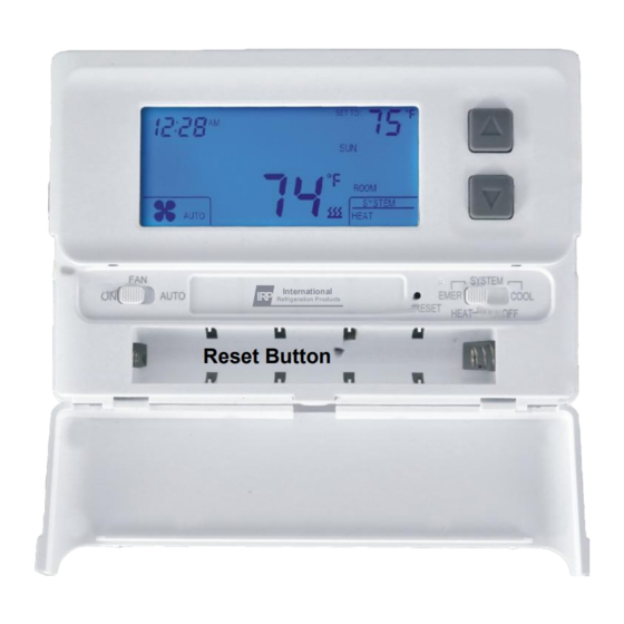
THERMOSTAT LIQUID CRYSTAL DISPLAY (LCD) Time & Day Setting Filter Service Reminder Low Battery Icon SET TO: Setpoint SERVICE FILTER CONFIG Cooling Icon Configuration ROOM COMP DELAY Compressor SYSTEM AUTO HEAT OFF COOL Lockout Delay System Mode EMH/HEAT/OFF/COOL Room Heating Icon ON/AUTO Temperature Figure 1... -
Page 4: Remove The Old Thermostat
REMOVE THE OLD THERMOSTAT WARNING! Electrical Shock Hazard 1. Turn off power to the thermostat at the main service panel by removing the fuse or switching the appropriate circuit breaker to the “OFF” position before removing the existing thermostat. 2. Turn off power to the heating and cooling system by removing the fuse or switching the appropriate circuit breaker to the “OFF”... -
Page 5: Install The New Thermostat
INSTALL THE NEW THERMOSTAT WARNING! Electrical Shock Hazard Ensure that power is turned off. See steps 1 and 2 in previous section. 1. Place the SYSTEM switch in the OFF position. (See Figure 2) 2. Place the FAN switch in the AUTO position. (See Figure 2) 3. -
Page 6: Configuration
8. Double check that each wire is connected to the proper terminal. Tighten the screws on the terminal block. Gently tug on each wire to ensure proper connection. 9. Set the FAN OPTION switch on the back of the front cover to the proper position. (See Figure 5 below) If your system REQUIRES the thermostat to turn on the fan during a call for emergency heat, such as electric strip heat, place the fan option switch in the ELEC position. -
Page 7: Configuration Menu Chart
thermostat will automatically exit to the OFF mode. Note: All changes made in the configuration menu are automatically saved. CONFIGURATION MENU CHART See “Parameters” section for a detailed explanation of parameters and values. Parameter Factory Parameter Value Description Defaults Options Select cooling cycle rate: FA or SL FA= fast SL = slow... - Page 8 AU - Select Auxiliary Heat Offset This feature allows you to select when the auxiliary heat system will turn on. This offset can be set from 1 to 10 (degrees), in 1° increments, and the auxiliary system will turn on (in addition to first stage of heat) when the room temperature is below the setpoint by the selected number of degrees plus heating cycle rate value (HC).
-
Page 9: System Check
SYSTEM CHECK If at any time during testing your system does not operate properly, contact a qualified HVAC contractor. Ensure that there is power to the system. Fan Operation (If your system does not have a “G” (Fan) terminal connection, skip to the “Heating System” section.) 1. -
Page 10: Basic Thermostat Operation
the switch stays in this position. 2. Adjust the setpoint to a temperature above the current room temperature. If the (FA)st heating cycle rate is selected in the configuration menu (see “Configuration Menu Chart”), the thermostat will call for emergency heat when the room temperature is 0.75º... -
Page 11: Troubleshooting
3. To turn the system off, move the SYSTEM switch to the OFF position and the FAN switch to the AUTO position. Filter Review 1. Move the SYSTEM switch to the EMH, HEAT, or COOL position, then press and hold the ▲ and ▼... -
Page 12: Warranty
INTERNATIONAL REFRIGERATION PRODUCTS CO., INC. LIMITED WARRANTY POLICY International Refrigeration Products Co., Inc. (Hereinafter referred to as IRP”) warrants the following: INTERNAT IONAL REFRIGERATION PRODUCTS CO ., INC. Only cataloged products sold to distributors are warranted to the original LI MIT ED WARRANTY POL ICY purchaser, to conform with specifications furnished or approved by IRP, and to be free from defects in material and workmanship, for a period of one (1) In te rn ati o na l Re frig e rati on Pr od uc ts Co., In c.
Need help?
Do you have a question about the SN12I and is the answer not in the manual?
Questions and answers