Advertisement
Quick Links
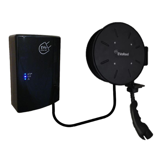
EVoReel
Electric Vehicle Charging Station
INSTALLATION GUIDE
AND USER MANUAL
Model: 30A EVoReel iEVSE
Model Numbers: EV072-110-001A, 002A, 003A, 011A, 012A, 013A
Product Safety Certification: Retractable Reel: ETL and cETL Listed; EVSE: UL and cUL Listed
Description: SAE J1772 AC Level 2, 30A Continuous Rated EVSE with Retractable Reel
Version 2.4
Advertisement

Subscribe to Our Youtube Channel
Related Manuals for EVoCharge 30A EVoReel iEVSE


Summary of Contents for EVoCharge 30A EVoReel iEVSE
-
Page 1: Installation Guide
Electric Vehicle Charging Station INSTALLATION GUIDE AND USER MANUAL Model: 30A EVoReel iEVSE Model Numbers: EV072-110-001A, 002A, 003A, 011A, 012A, 013A Product Safety Certification: Retractable Reel: ETL and cETL Listed; EVSE: UL and cUL Listed Description: SAE J1772 AC Level 2, 30A Continuous Rated EVSE with Retractable Reel... - Page 2 ©2012-2015 EVoCharge - All Rights Reserved All information in this document is subject to copyright and other intellectual property rights of EVoCharge. This material may not be modified, reproduced or copied, in whole or in part, without the prior written permission of EVoCharge. EVoCharge and EVoReel are trademarks of EVoCharge.
-
Page 3: Table Of Contents
CONTENTS SAFETY INFORMATION………………………………………………….4-5 IMPORTANT REFERENCE INFORMATION………………….……6 SPECIFICATIONS……………………………………………………….….. 7 FEATURES……………………………………………………………….…….8 INSTALL PLANNING AND SERVICE WIRING…………………… 9 INSTALLATION………………………………………………………..….… 10-23 OPERATION………………………………………..…………………………24-26... -
Page 4: Safety Information
• Do not attempt to open, disassemble, repair, tamper with, or modify the Charging Station. The Charging Station is not user serviceable. Contact EVoCharge for any repairs. • Do not use the Charging Station when either you, the vehicle, or the Charging Station is exposed to severe rain, snow, electrical storm or other severe weather. - Page 5 SAVE THESE SAFETY INSTRUCTIONS This document contains important instructions and warnings that must be followed when installing and maintaining the Charging Station Caution • Incorrect installation and testing of the Charging Station could potentially damage either the vehicle’s Battery and/or the Charging Station itself.
-
Page 6: Important Reference Information
Do not attempt to open, disassemble, repair, tamper with, or modify any components of the products – the products are not user serviceable. Contact EVoCharge for any repairs •... -
Page 7: Specifications
SPECIFICATIONS EV072-110-002A: RFID/Networked iEVSE, 3 ft. Interconnect, 30 ft. Charge Cable Part Numbers EV072-110-001A: RFID/Networked iEVSE, 10 ft. Interconnect, 30 ft. Charge Cable EV072-110-003A: RFID/Networked iEVSE, 20 ft. Interconnect, 30 ft. Charge Cable Connector / EVSE Level SAE J1772; AC Level 2 Max Output Rating 30A;... -
Page 8: Features
FEATURES Retractable Reel All EVoReel Charging Stations provide added convinience to the user by utilizing a retractable reel for charge cable management. The retractable reel includes a vehicle charge cable up to 30 feet in length. Indoor/Outdoor Rated Enclosures (NEMA 3R) The EVoReel Charging Stations are rated for both indoor and outdoor charging and comply with NEMA 3R standards. -
Page 9: Install Planning And Service Wiring
• 30A EVoReel iEVSE product only: To allow for network connection – install a standard CAT5/6 network cable to the unit. The CAT5/6 network cable connects to the Ethernet port at the bottom of the EVSE. -
Page 10: Installation
INSTALLATION Retractable Reel STEP 1 – Verify Received Content Mounting Interconnect Support Clamp Bracket Quantity (4) (For use to support Interconnect cable following installation) 3/8” Lag Screws Quantity: (3) Charge Cable (For use when mounting reel to wall/ceiling wooden wall stud) Vehicle 1/4”... - Page 11 INSTALLATION STEP 2 – Adjust Retractable Reel Roller Guide Arm Position 1. Prior to mounting retractable reel, determine the preferred position of the roller guide arm. The roller guide arm can be adjusted into (12) different locations based on your installation method.
- Page 12 INSTALLATION STEP 3 – Install Retractable Reel 1. Determine preferred height and orientation of retractable reel. It is recommended to install retractable reel at the maximum height based on interconnect cable length. The retractable Mounting Option “A” reel can be mounted using mounting option “A”...
- Page 13 INSTALLATION STEP 4 – Install Retractable Reel 1. Locate a wall stud and use a 1/4” bit to drill a pilot hole for each mounting hole. The (3) mounting holes are positioned 1.625” away from each other. 2. Prepare mounting hole by Fastening lag screw into top of 1.625”...
- Page 14 INSTALLATION STEP 5 – Install Retractable Reel 1. Place reel mounting bracket over mounting holes and fasten lag screw. 2. Continue fastening lag screws into each mounting hole. WARNING: All lag screws MUST be used to install the charging unit to the vertical wall stud.
- Page 15 INSTALLATION STEP 6 – Adjust Vehicle Connector Position 1. Adjust retractable reel ball stop position by using a screwdriver to loosen both fasteners. 2. Adjust the ball stop to a position that enables a convenient vehicle connector rest position. 3. Fasten and secure the ball stop to vehicle charge cable.
- Page 16 INSTALLATION STEP 7 – Adjust Reel Retraction Rate (if required) 1. Depending on the cable stop placement from installation step 6, the retraction rate of the reel may need adjustment. This can be accomplished by manually adjusting the number of charge cable wraps around the reel.
- Page 17 INSTALLATION STEP 8 – Mounting the Charging Unit...
- Page 18 INSTALLATION STEP 8 – Mounting the Charging Unit...
- Page 19 INSTALLATION STEP 8 – Mounting the Charging Unit...
- Page 20 INSTALLATION STEP 8 – Mounting the Charging Unit...
- Page 21 INSTALLATION STEP 8 – Mounting the Charging Unit...
- Page 22 INSTALLATION STEP 9 – Connecting Charging Unit to NEMA 6-50 Outlet...
- Page 23 (OPTIONAL) INSTALLATION STEP 9 – Hardwire Connection...
- Page 24 OPERATION – Enable Charging IMPORTANT: Once the charging unit is connected to supply-power, turn- on the charging unit by placing the toggle switch towards the front of the charging unit. The toggle switch is located at the bottom of the charging unit.
- Page 25 OPERATION – Disable Charging 1. Remove charge connector from vehicle and pull slightly on the charge cable to retract the cable onto the reel and place charge connector in its stowed position. 2. Ready Indicator (Green Color) is present and the charging unit is ready for the next charge cycle.
-
Page 26: Operation
The ON position is with the toggle switch positioned toward the front of the charging unit. Note: Contact a qualified electrical personnel or EVoCharge if resetting the charging unit does not clear the Fault LED indicator. - Page 27 EVoReel Electric Vehicle Cable Management sales@evocharge.com (800) 930-9450 For the latest user manual version, please visit www.evocharge.com/download.html...
Need help?
Do you have a question about the 30A EVoReel iEVSE and is the answer not in the manual?
Questions and answers